
Flange connections are a common and key component in piping and equipment systems, used to connect pipe sections, valves, pumps, and other components. The integrity of flange connections is directly linked to the safety and stable operation of the entire system. In flange connections, bolts play a key role in maintaining the integrity of the pipeline system. They must be tightened with sufficient torque to ensure that the system remains leak-free and functional despite pressure fluctuations, thermal expansion, or mechanical vibrations. Flange bolt torque technology involves controlling the tightening force through preset torque values ensuring uniformity and repeatability in bolt connections. Following the correct tightening sequence helps distribute torque evenly and reduces wear and deformation risks. So, how to ensure the correctness of the torque? Here we show you how to ensure accurate Flange bolt torque and tightening sequence so that you can easily grasp the correct.

1. Flange Bolt Torque Value
When performing a flange connection, selecting the correct torque value is essential. This information is typically found in the equipment manual or legal standards. If not available, consulting the equipment manufacturer or a technical expert is advisable. It’s important to note that torque values may change over time and with pressure variations, so regular checks and recalibrations are necessary. Following the correct tightening sequence helps distribute torque evenly and reduces wear and deformation risks. Here’s how to ensure accurate Flange bolt torque and tightening sequence:
1.1. What is Flange Bolt Torque?
Flange torque is the force needed to assemble or disassemble connected flanges. It depends on factors like flange size, material, overlap area, and gasket type. Suitable flange torque should be based on specific circumstances and relevant standards, with adjustments as needed.
1.2. Flange Bolt Torque Standard: ASME
Determining the appropriate flange tightening torque requires reference to relevant standards, among which the more common ones are ASME standards and DIN standards. The ASME standard specifies the tightness requirements and tightening torque range of the flange, while the DIN standard is responsible for specifying the type and specification of the flange. These standards are important for both installation and maintenance work, so they need to be fully understood and followed during work.
1.3. ASME Flange Bolt Torque Value Chart
The following are general reference tables to ASME Flange Bolt Torque Standard. These reference parameters are based on the flange bolt tightening torque calculated under the condition that the operating pressure is regarded as the nominal pressure and the operating temperature is equivalent to 150 degrees Celsius. In general, the following parameters are directly adopted:
a) ASME/ANSI CLASS 900 Flange Blot Torque Chart (25Cr2MoVA Blot)
- Flange pressure rating: PN15.0 MPa (equivalent to ANSI CLASS 900);
- Bolt material: 25Cr2MoVA;
- Gasket shape: Ring type;
- Gasket material: Stainless steel and soft steel.
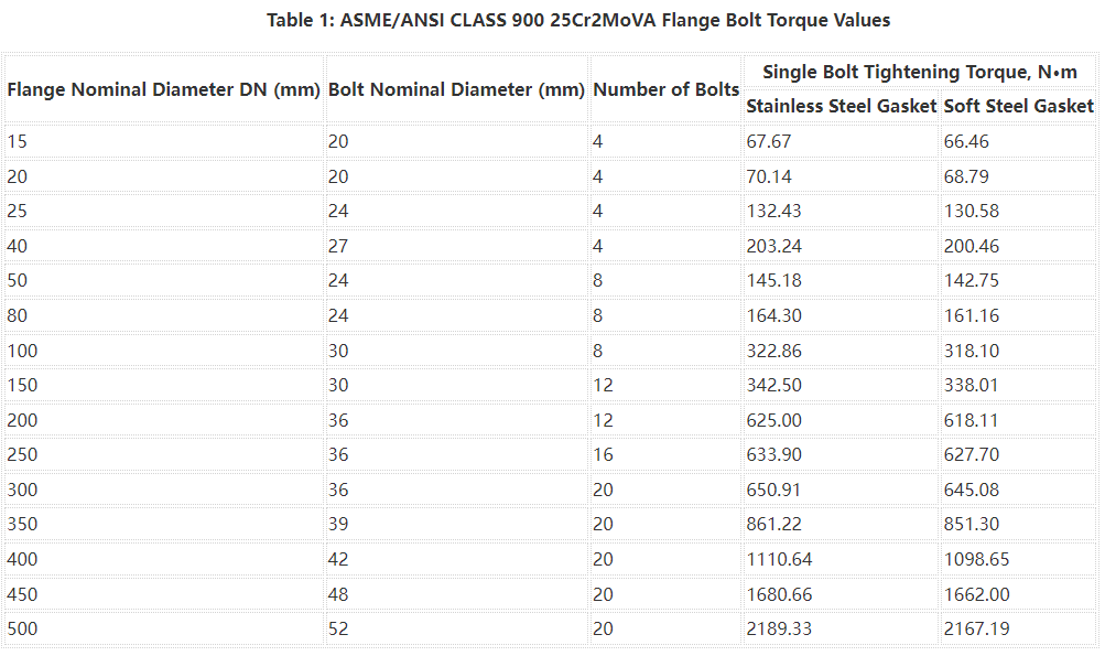
Table 1 lists the flange bolt tightening torques for various nominal diameters under the above conditions.
b) ASME/ANSI CLASS 900 Flange Blot Torque Chart (35CrMoA Blot)
- Flange pressure rating: PN15.0 MPa (equivalent to ANSI CLASS 900);
- Bolt material: 35CrMoA;
- Gasket shape: Ring type;
- Gasket material: Stainless steel and soft steel.
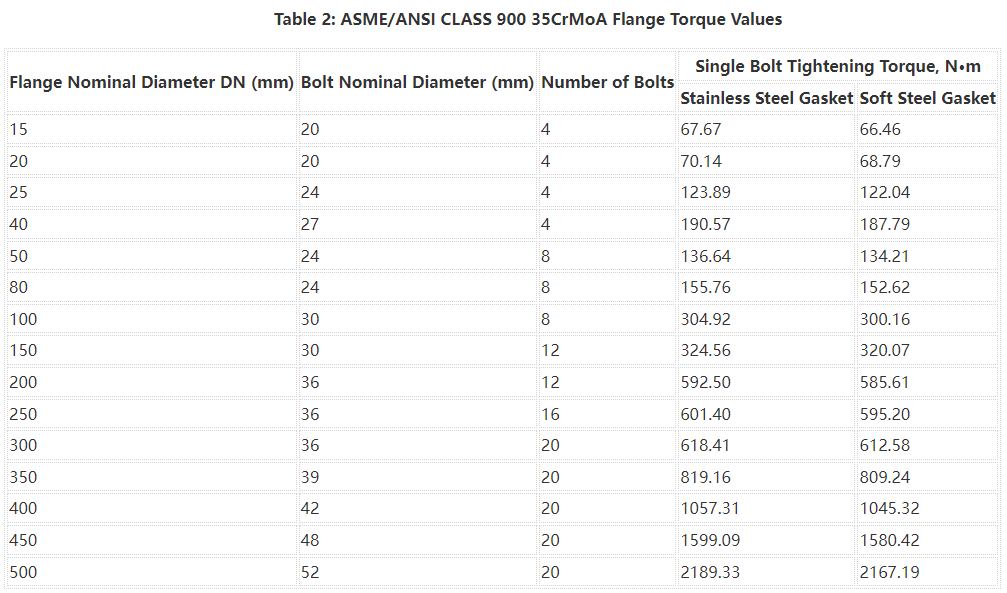
Table 2 lists the flange bolt tightening torques for various nominal diameters under the above conditions.
c) ASME/ANSI CLASS 1500 Flange Blot Torque Chart (25Cr2MoVA Blot)
- Flange pressure rating: PN25.0 MPa (equivalent to ANSI CLASS 1500);
- Bolt material: 25Cr2MoVA;
- Gasket shape: Ring type;
- Gasket material: Stainless steel and soft steel.
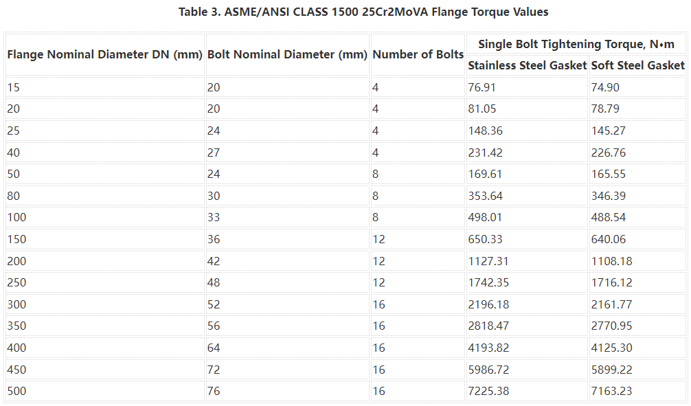
Table 3 lists the flange bolt tightening torques for various nominal diameters under the above conditions.
d) ASME/ANSI CLASS 1500 Flange Blot Torque Chart (35CrMoA Blot)
- Flange pressure rating: PN25.0 MPa (equivalent to ANSI CLASS 1500);
- Bolt material: 35CrMoA;
- Gasket shape: Ring type;
- Gasket material: Stainless steel and soft steel.
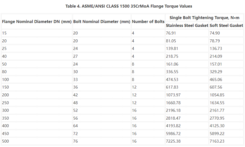
Table 4 lists the flange bolt tightening torques for various nominal diameters under the above conditions.
e) ASME/ANSI CLASS 2500 Flange Blot Torque Chart (25Cr2MoVA Blot)
- Flange pressure rating: PN42.0 MPa (equivalent to ANSI CLASS 2500);
- Bolt material: 25Cr2MoVA;
- Gasket shape: Ring type;
- Gasket material: Stainless steel and soft steel.
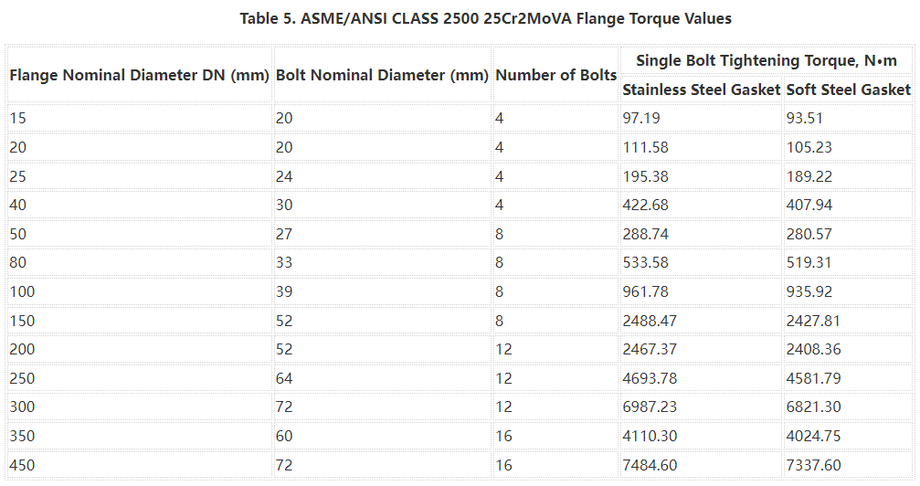
Table 5 lists the flange bolt tightening torques for various nominal diameters under the above conditions.
f) ASME/ANSI CLASS 2500 Flange Blot Torque Chart (35CrMoA Blot)
- Flange pressure rating: PN42.0 MPa (equivalent to ANSI CLASS 2500);
- Bolt material: 35CrMoA;
- Gasket shape: Ring type;
- Gasket material: Stainless steel and soft steel.
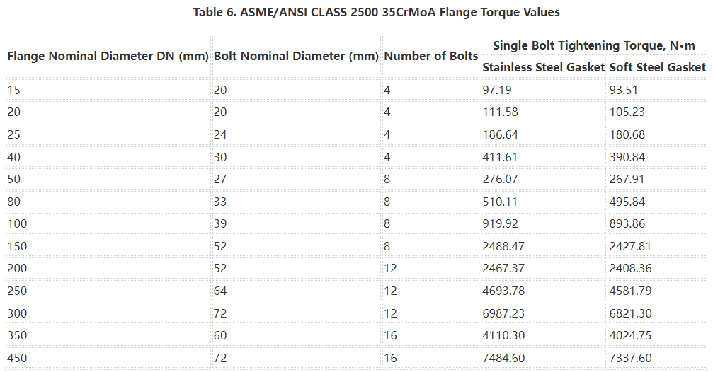
Table 6 lists the flange bolt tightening torques for various nominal diameters under the above conditions.
1.4. Flange Bolt Torque Calculation Formula
The formula for calculating flange bolt torque is:
T=(P*DN)/(2*π*K)
Where T is the torque in Newton-meters (Nm), P is the pressure on the flange surface in Megapascals (MPa), DN is the nominal diameter of the flange in millimeters (mm), and K is the coefficient of friction, typically taken as 0.2.
Notes:
In practical applications, in order to calculate a more reasonable flange torque, the following points need to be considered:
(1) Selection of flange standards and materials. Flanges of different standards and materials have different specifications, sizes and load-bearing capacities, so they need to be distinguished when calculating flange torque.
(2) The influence of installation conditions. For example, the cleanliness of the flange connection surface, lubricating grease, and tightening degree will affect the calculation of flange torque and the effect in actual use.
(3) The influence of flange connection method. For example, the specifications and quantity of the connecting bolts, the tightening sequence, etc. will affect the size of the flange torque and the application effect.
2. Flange Bolt Torque Sequence (Pattern)
Understanding the correct bolt tightening sequence ensures product quality and safety:
2.1. What is Flange Bolt Torque Sequence?
The sequence determines the uniform load on the flange surface. Following the proper order helps distribute torque evenly, reducing wear and deformation risks. Incorrect sequences can lead to uneven loads, product damage, or safety hazards.
2.2. Flange Bolt Tightening Sequence Chart & Pattern
Formulating the correct flange torque sequence table can ensure work safety and product quality and performance. The following is a flange torque sequence table summarized from experience:
| Number of Blots | Flange Torque Sequence |
|---|---|
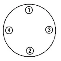
| 4 Blot Flange Torque Sequence | 1→3→2→4 |
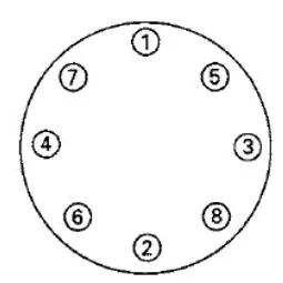
| 8 Blot Flange Torque Sequence | 1→5→3→7, 2→6→4→8 |
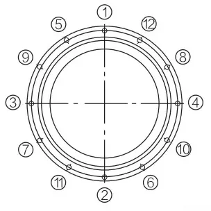
| 12 Blot Flange Torque Sequence | 1→7→4→10, 2→8→5→11, 3→9→6→12 |
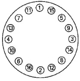
| 16 Blot Flange Torque Sequence | 1→9→5→13, 3→11→7→15, 2→10→6→14, 4→12→8→16 |
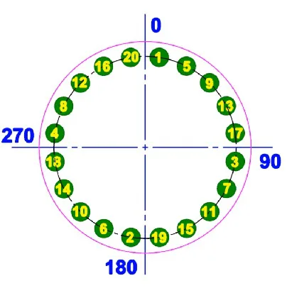
| 20 Blot Flange Torque Sequence | 1→11→6→16, 3→13→8→18, 5→15→10→20, 2→12→7→17, 4→14→9→19 |
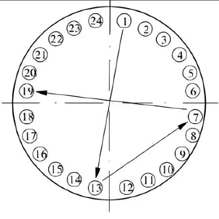
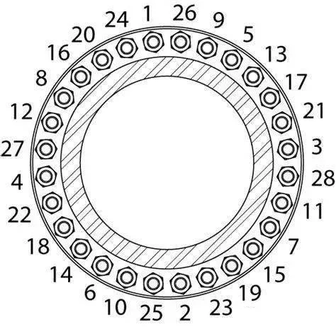
| 24 Blot Flange Torque Sequence | 1→13→7→9, 4→16→10→22, 2→14→8→20, 5→17→11→23, 3→15→9→21, 6→18→12→24 |
| 28 Blot Flange Torque Sequence | 1→15→8→22, 4→18→11→25, 7→21→14→28, 2→16→9→23, 5→19→12→26, 3→17→10→24, 6→20→13→27 |
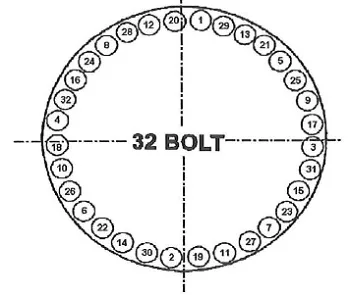
| 32 Blot Flange Torque Sequence | 1→17→9→25, 5→21→13→29, 3→19→11→27, 7→23→15→31, 2→18→10→26, 6→22→14→30, 4→20→12→28, 8→24→16→32 |
| 36 Blot Flange Torque Sequence | 1→19→10→28, 5→23→14→32, 9→27→18→36, 3→21→12→30, 7→25→16→34, 2→20→11→29, 6→24→15→33, 4→22→13→31, 8→26→17→35 |
| 40 Blot Flange Torque Sequence | 1→21→11→31, 6→26→16→36, 3→23→13→33, 8→28→18→38, 5→25→15→35, 9→29→19→39, 2→22→12→32, 7→27→17→37, 4→24→14→34, 10→30→20→40 |
| 68 Blot Flange Torque Sequence | 1→35→18→52, 9→43→26→60, 5→39→22→56, 13→47→30→64, 3→37→20→54, 11→45→28→62, 7→41→24→58, 15→49→32→66, 2→36→19→53, 10→44→27→61, 6→40→23→57, 17→51→34→68, 4→38→21→55, 12→46→29→63, 8→42→25→59, 16→50→33→67, 14→48→31→65 |
To help you understand the Flange Bolt Torque Sequence more clearly, we show the tigtening patterns of different numbers of flange bolts:
4 Blot Flange Torque Pattern
8 Blot Flange Torque Pattern
10 Blot Flange Torque Pattern

12 Blot Flange Torque Pattern
16 Blot Flange Torque Pattern
20 Blot Flange Torque Pattern
24 Blot Flange Torque Pattern
28 Blot Flange Torque Pattern
32 Blot Flange Torque Pattern
2.3. Flange Bolt Tightening Sequence Principles
The tightening order of flange bolts determines the uniform load on the flange surface, so they must be tightened in a certain order. The specific steps are as follows:
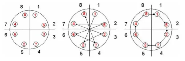
Cross-symmetry principle. Usually, flange bolts are installed in pairs, and the connection surfaces between the two nuts connected by each pair of bolts are parallel. When tightening the bolts, it is necessary to start from both sides of the bolt pair and tighten alternately to the middle to ensure balanced distribution of force and reduce deformation.
Low-first-high-later principle. On the basis of the cross-symmetry principle, the flange bolts should also be tightened according to the height relationship of the position. Specifically, it is necessary to start tightening from the low position and gradually move to the high position.
Multiple reciprocating principle. When tightening the flange bolts, it is recommended to tighten them back and forth multiple times to ensure that all threads are fully locked and the load and deformation are balanced.
Notes:
When performing the flange torque operation, it is best to use a manual tightening method, which will make it easier to grasp the torque value and sequence.
When installing the flange, be sure to carefully check and clean its surface to ensure a tight fit.
When tightening the nut, thread lubricant must be added to make the thread rotate easily and reduce friction.
When performing the final tightening, the correct torque value must be used to ensure that all bolts are tightened to the appropriate torque value.
Related Articles:
 Machining Material Density Chart – Density Unit Conversion Table
 What Is a Blind Flange – Blind Flange Dimensions Chart in MM & Inch (Class 150 to 2500)
 Sprocket Types & Size Chart (Pitch Diameter, Specs, Uses, Design) | Chain Sprocket Catalogue
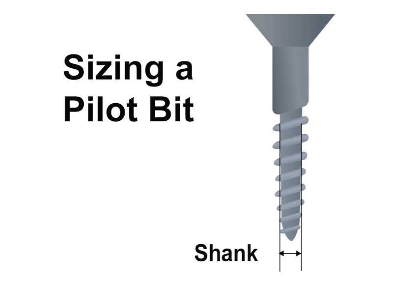 Pilot Hole Drill Bit Size Chart for Wood, Sheet Metal, Lag Screws
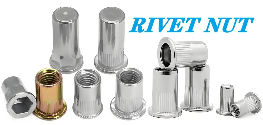 Rivnut Hole & Drill Size Chart | Rivet Nut Sizes, Types, Installation
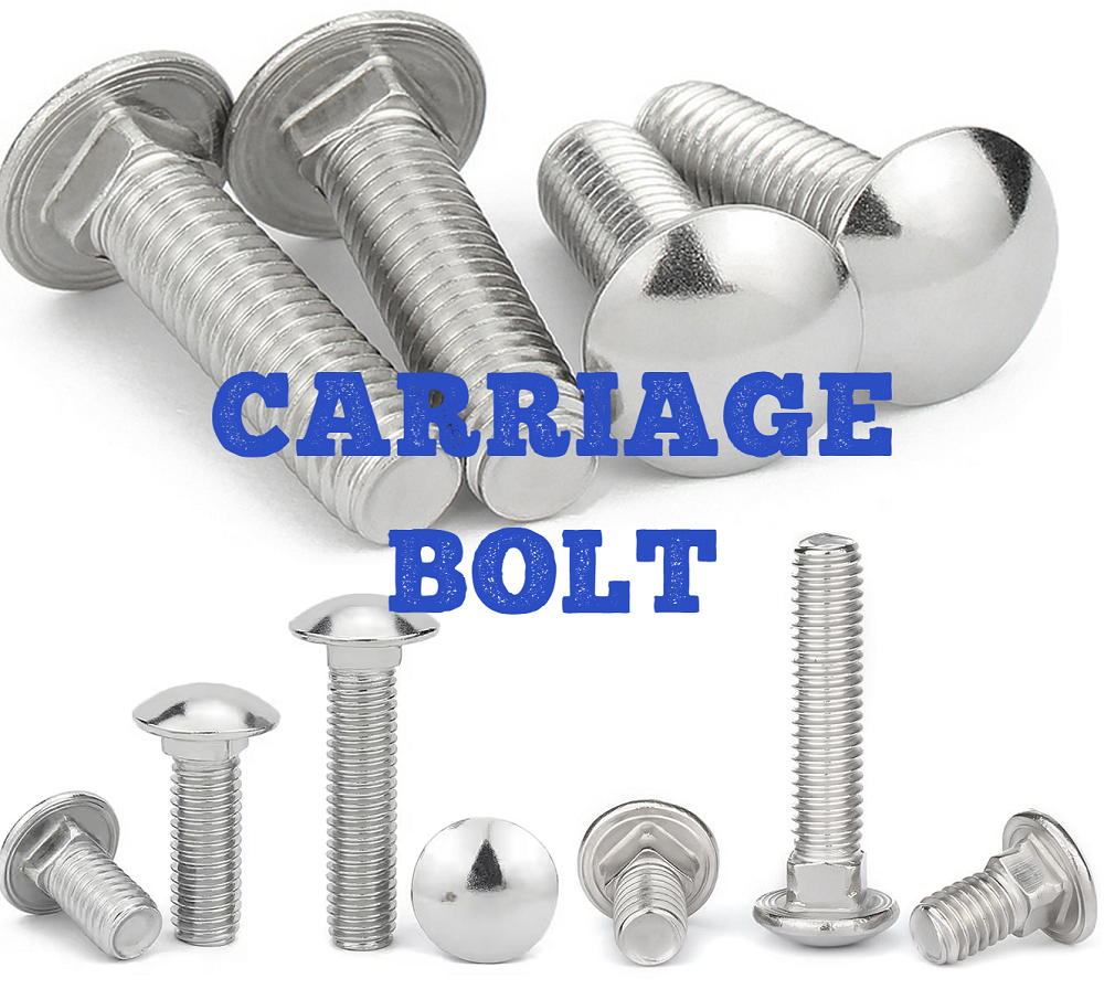 Carriage Bolt Definition, Dimensions, Types, Grades, Torque, Uses, Carriage vs Lag Bolt