Buttress threads are a go-to solution for handling heavy axial loads in one direction, thanks to their unique trapezoidal design. With a steep “stabbing flank” and a shallower “bearing flank,” they provide high load capacity, reliable self-locking, and smooth engagement. You’ll find these threads in applications like screw jacks, clamps, hydraulic systems, and oilfield equipment, where strength and efficiency are key. Here, we’ll break down buttress thread dimensions in both metric (mm) and imperial (inch), cover the standard angles from ISO, ANSI, DIN, and API, types, uses, and include a calculator to make sizing simple. If you work with heavy-duty machinery or precision systems, this is the resource you need.
What is Buttress Thread?
Buttress thread, also known as bevel thread or trapezoidal thread, is a type of thread profile characterized by its asymmetric shape. It consists of one side with a steep leading edge (stabbing flank) and a slightly angled trailing edge (bearing flank). This unique design allows buttress threads to withstand high axial forces predominantly in one direction while enabling smooth engagement and disengagement.
Related Read:
- Pilot Hole Size Chart for Metal, Wood, Lag Screws & Bolts
- Shaft Key Drill Size Chart (Metric & Imperial)
Buttress threads are commonly used in applications that require efficient transmission of axial force in one direction, such as screw jacks for lifting heavy loads, vises and clamps for securing workpieces, and hydraulic and pneumatic cylinders for converting fluid pressure into linear motion. They are represented by the symbol “Bu”.
Buttress Thread Angle in Different Standards & Applications
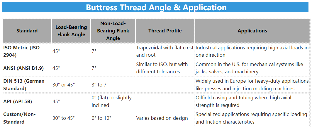
The cross-section of a buttress thread presents a trapezoidal shape. The stabbing flank typically has a steep angle of 45° or 7°, while the bearing flank has a shallower angle of 7° or 45°, respectively. This asymmetric profile provides high load capacity and self-locking behavior, making buttress threads suitable for applications requiring strong connections, especially under high internal pressure.
Here are the buttress thread angles according to various standards such as ISO, ANSI, DIN, and others. Each standard specifies slightly different angles depending on the application:
Here’s a simple diagram showing the typical profile of a buttress thread:

Buttress Thread Types & Uses
Buttress threads, due to their unique shape and structure, have wide applications in many fields. Below, we will use a table to show in detail the main types of buttress threads and their characteristics and uses.
| Buttress Thread Type | Feature | Typical Uses |
|---|---|---|
| Unidirectional Buttress Thread | Thread slants in one direction, easy to insert | Fastening parts, connecting parts |
| Bidirectional Buttress Thread | Thread slants in both directions, easy to unscrew | Situations requiring frequent assembly/disassembly |
| High-strength Buttress Thread | High strength, strong load capacity | Heavy machinery, bridge beams |
| Self-locking Buttress Thread | Self-locking, prevents loosening | Vibrating environments, key connections |
Buttress Thread Size Chart (Metric)
The following table provides the dimensional standards for buttress threads in metric units (mm):
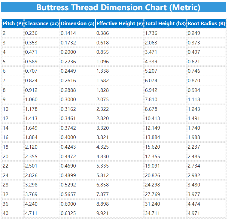
Note: Refer to the attached PDF for the complete dimensional chart.
The chart includes the following parameters:
- d: Nominal diameter
- P: Pitch
- d: Major diameter
- d2 = D2: Pitch diameter
- d3: Minor diameter
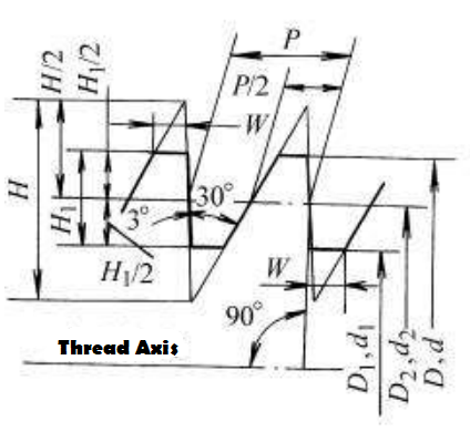
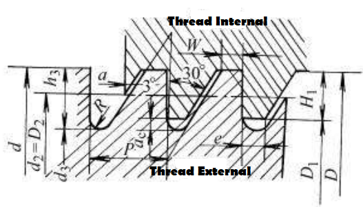
- H: Total thread height, H = 1.5878P
- H1: Height of load-bearing portion, H1 = 0.75P
- h3: Total thread height including clearance, h3 = H1 + ac
- ac: Clearance distance, ac = 0.11777P
- e: Effective thread height, e = W – ac
- R: Root radius, R = 0.12427P
Buttress Thread Chart PDF (MM/Inches)
For a complete reference of buttress thread dimensions, you can download the PDF chart attached to this article. The chart provides an extensive list of nominal diameters, pitches, and corresponding dimensional parameters in both metric (mm) and imperial (inch) units.
Buttress Thread Dimension Calculator (Formula)
To assist in selecting the appropriate buttress thread for your application, a calculator can be beneficial. The following shows you how to calculate each specific parameters such as diameter, pitch, and load requirements, to find the optimal thread specifications:
| Term | Symbol | Formula |
| Nominal Diameter | d | D=d |
| Major Diameter | D | D=d |
| Pitch | P | |
| Clearance | ac | ac=0.117767P |
| Height of Load-bearing Part | Hi | H=0.75P |
| Total Thread Height | h3 | h3=Hi + Si=0.867767P |
| Pitch Diameter | d2 | d2=d−H−d=0.75P |
| Pitch Diameter (Major) | D2 | D2=d2 |
| Minor Diameter | d3 | d3=d−2H3=d−0.867767P |
| Minor Diameter (Major) | Di | Di=d−2Hi=d−1.5P |
| Root Radius | R | R=0.124271P |
For a screw with a nominal diameter of 40mm and a pitch of 7mm, the key engagement length should be: B40 × 7.
For a screw with a nominal diameter of 40mm and a pitch of 7mm, the key engagement length should be: B40 × 14 (P7) LH.


