
A clearance hole is necessary to permit a fastener to pass through a material without its threads gripping into it, what size should a clearance hole be for different fasteners such as a M4 screw or a 3/8 bolt. To determine its diameter, check out the clearance hole size chart for metric and imperial bolts, screws, and studs according to ASME B18.2.8 standard.
![]()
What Is Clearance Hole?
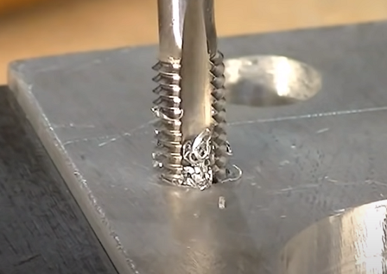
A clearance hole is a specific type of hole drilled in a material that is designed to allow a threaded fastener to pass through without engaging the threads. Is is distinct from a tapping drill hole, which is used to prepare a material for internal threading. The clearance hole is slightly larger than the nominal diameter of the bolt or screw it’s intended for, ensuring that the fastener can pass through freely. This is crucial in engineering applications where components need to be joined together using threaded fasteners, as it allows for easy assembly and disassembly without the fastener binding in the material it’s passing through.
How to Determine the Clearance Hole Diameter?
Engineers usually use standard charts or tables to determine the clearance hole size, and they provide the recommended dimensions based on the fastener size. The corresponding clearance hole diameter can be obtained based on the thread size. For example, an M12 screw requires a clearance hole of 13.5 to 13.77 mm for a normal fit. The clearance hole size is always slightly larger than the nominal thread size to accommodate manufacturing tolerances and ensure smooth assembly.
How to Calculate the Clearance Hole Diameter?
The calculation is based on the GD&T positional tolerance method.
1) Formula:
Minimum Clearance Hole Diameter (H1) = F + T1 + T2 × (1 + 2 × (P/D))
Nominal Clearance Hole Diameter (H2) = H1 + |Lower Size Tolerance|
2) Parameters:
F: Maximum fastener diameter (nominal thread size)
T1: Positional tolerance for clearance holes
T2: Positional tolerance for threaded holes
P: Maximum length of clearance hole
D: Minimum thread depth
3) Calculation Steps:
Step 1: Calculate the Minimum Clearance Hole Diameter (H1)
Input the values: F = 0.25, T1 = 0.007, T2 = 0.014, P = 0.755, D = 0.5
Calculate: H1 = F + T1 + T2 × (1 + 2 × (P/D))
Calculate: H1 = 0.25 + 0.007 + 0.014 × (1 + 2 × (0.755/0.55)) = 0.3133 (round up to 0.3133 to ensure interference-free assembly)
Step 2: Determine Size Tolerance
Use a low-cost drill tolerance table to determine the size tolerance based on the minimum clearance hole diameter (H1). In this case, H1 = 0.3133 falls between 0.201 and 0.400, so the size tolerance is +0.007, -0.002.
Step 3: Calculate the Nominal Clearance Hole Diameter (H2)
Plug in the values: H1 = 0.3133, Lower Size Tolerance = -0.002
Calculate: H2 = H1 + |Lower Size Tolerance|
Calculate: H2 = 0.3133 + |-0.002| = 0.3133 + 0.002 = 0.3153
Select the next larger standard drill bit available, which is a letter O drill bit with a diameter of 0.316. This is the practical choice for the clearance hole diameter.
Clearance Hole Sizes & Dimensions (ASME B18.2.8) for Bolts, Screws and More Fasteners
- Metric Clearance Hole Size Chart (MM)
| Nominal Screw Size | Normal Tolerance | Close Tolerance | Loose Tolerance | ||||||
| Nominal Drill Size | Hole Diameter | Nominal Drill Size | Hole Diameter | Nominal Drill Size | Hole Diameter | ||||
| Min. | Max. | Min. | Max. | Min. | Max. | ||||
| M1.6 | 1.8 | 1.8 | 1.94 | 1.7 | 1.7 | 1.8 | 2 | 2 | 2.25 |
| M2 | 2.4 | 2.4 | 2.54 | 2.2 | 2.2 | 2.3 | 2.6 | 2.6 | 2.85 |
| M2.5 | 2.9 | 2.9 | 3.04 | 2.7 | 2.7 | 2.8 | 3.1 | 3.1 | 3.4 |
| M3 | 3.4 | 3.4 | 3.58 | 3.2 | 3.2 | 3.32 | 3.6 | 3.6 | 3.9 |
| M4 | 4.5 | 4.5 | 4.68 | 4.3 | 4.3 | 4.42 | 4.8 | 4.8 | 5.1 |
| M5 | 5.5 | 5.5 | 5.68 | 5.3 | 5.3 | 5.42 | 5.8 | 5.8 | 6.1 |
| M6 | 6.6 | 6.6 | 6.82 | 6.4 | 6.4 | 6.55 | 7 | 7 | 7.36 |
| M8 | 9 | 9 | 9.22 | 8.4 | 8.4 | 8.55 | 10 | 10 | 10.36 |
| M10 | 11 | 11 | 11.27 | 10.5 | 10.5 | 10.68 | 12 | 12 | 12.43 |
| M12 | 13.5 | 13.5 | 13.77 | 13 | 13 | 13.18 | 14.5 | 14.5 | 14.93 |
| M14 | 15.5 | 15.5 | 15.77 | 15 | 15 | 15.18 | 16.5 | 16.5 | 16.93 |
| M16 | 17.5 | 17.5 | 17.77 | 17 | 17 | 17.18 | 18.5 | 18.5 | 19.02 |
| M20 | 22 | 22 | 22.33 | 21 | 21 | 21.21 | 24 | 24 | 24.52 |
| M24 | 26 | 26 | 26.33 | 25 | 25 | 25.21 | 28 | 28 | 28.52 |
| M30 | 33 | 33 | 33.39 | 31 | 31 | 31.25 | 35 | 35 | 35.62 |
| M36 | 39 | 39 | 39.39 | 37 | 37 | 37.25 | 42 | 42 | 42.62 |
| M42 | 45 | 45 | 45.39 | 43 | 43 | 43.25 | 48 | 48 | 48.62 |
| M48 | 52 | 52 | 52.46 | 50 | 50 | 50.25 | 56 | 56 | 56.74 |
| M56 | 62 | 62 | 62.46 | 58 | 58 | 58.3 | 66 | 66 | 66.74 |
| M64 | 70 | 70 | 70.46 | 66 | 66 | 66.3 | 74 | 74 | 74.74 |
| M72 | 78 | 78 | 78.46 | 74 | 74 | 74.3 | 82 | 82 | 82.87 |
| M80 | 86 | 86 | 86.54 | 82 | 82 | 82.35 | 91 | 91 | 91.87 |
| M90 | 96 | 96 | 96.54 | 93 | 93 | 93.35 | 101 | 101 | 101.87 |
| M100 | 107 | 107 | 107.54 | 104 | 104 | 104.35 | 112 | 112 | 112.87 |
- Imperial Clearance Hole Size Chart (Inch)
| Nominal Screw Size | Normal Tolerance | Close Tolerance | Loose Tolerance | ||||||
| Nominal Drill Size | Hole Diameter | Nominal Drill Size | Hole Diameter | Nominal Drill Size | Hole Diameter | ||||
| Min. | Max. | Min. | Max. | Min. | Max. | ||||
| #0 | #48 | 0.076 | 0.082 | #51 | 0.067 | 0.071 | 3/32 | 0.094 | 0.104 |
| #1 | #43 | 0.089 | 0.095 | #46 | 0.081 | 0.085 | #37 | 0.104 | 0.114 |
| #2 | #38 | 0.102 | 0.108 | 3/32 | 0.094 | 0.098 | #32 | 0.116 | 0.126 |
| #3 | #32 | 0.116 | 0.122 | #36 | 0.106 | 0.110 | #30 | 0.128 | 0.140 |
| #4 | #30 | 0.128 | 0.135 | #31 | 0.120 | 0.124 | #27 | 0.144 | 0.156 |
| #5 | 5/32 | 0.156 | 0.163 | 9/64 | 0.141 | 0.146 | 11/64 | 0.172 | 0.184 |
| #6 | #18 | 0.170 | 0.177 | #23 | 0.154 | 0.159 | #13 | 0.185 | 0.197 |
| #8 | #9 | 0.196 | 0.203 | #15 | 0.180 | 0.185 | #3 | 0.213 | 0.225 |
| #10 | #2 | 0.221 | 0.228 | #5 | 0.206 | 0.211 | B | 0.238 | 0.250 |
| 1/4 | 9/32 | 0.281 | 0.290 | 17/64 | 0.266 | 0.272 | 19/64 | 0.297 | 0.311 |
| 5/16 | 11/32 | 0.344 | 0.354 | 21/64 | 0.328 | 0.334 | 23/64 | 0.359 | 0.373 |
| 3/8 | 13/32 | 0.406 | 0.416 | 25/64 | 0.391 | 0.397 | 27/64 | 0.422 | 0.438 |
| 7/16 | 15/32 | 0.469 | 0.479 | 29/64 | 0.453 | 0.460 | 31/64 | 0.484 | 0.500 |
| 1/2 | 9/16 | 0.562 | 0.572 | 17/32 | 0.531 | 0.538 | 39/64 | 0.609 | 0.625 |
| 5/8 | 11/16 | 0.688 | 0.698 | 21/32 | 0.656 | 0.663 | 47/64 | 0.734 | 0.754 |
| 3/4 | 13/16 | 0.812 | 0.824 | 25/32 | 0.781 | 0.789 | 29/32 | 0.906 | 0.926 |
| 7/8 | 15/16 | 0.938 | 0.950 | 29/32 | 0.906 | 0.914 | 1-1/32 | 1.031 | 1.051 |
| 1 | 1-3/32 | 1.094 | 1.106 | 1-1/32 | 1.031 | 1.039 | 1-5/32 | 1.156 | 1.181 |
| 1-1/8 | 1-7/32 | 1.219 | 1.235 | 1-5/32 | 1.156 | 1.164 | 1-5/16 | 1.312 | 1.337 |
| 1-1/4 | 1-11/32 | 1.344 | 1.360 | 1-9/32 | 1.281 | 1.291 | 1-7/16 | 1.438 | 1.463 |
| 1-3/8 | 1-1/2 | 1.500 | 1.516 | 1-7/16 | 1.438 | 1.448 | 1-39/64 | 1.609 | 1.634 |
| 1-1/2 | 1-5/8 | 1.625 | 1.641 | 1-9/16 | 1.562 | 1.572 | 1-47/64 | 1.734 | 1.759 |
Related Articles:
 Spindle Bearing of Lathe – Adjustment of Radial Clearance and Axial Clearance
 What is A Blind Hole – How to Get Perfect Blind Hole Threads
 What is Axial Force – Axial Force Definition, Diagram, Formula (Equation) & How To Calculate?
 Steps & Requirements Of Wire EDM Machining – How To Reduce The Human Error In WEDM
 Pilot Hole Size Chart: What Size A Pilot Hole Should Be for Screws
 Drill Bit Selection Guide – How to Select a Right Drill | CNCLATHING