- Home
- Machining techniques
- CNC Machining Services
- Cooperative supply services
- Designs
- Materials
- Finishing Services
- Shop
- Products
- Guide
- About Us
- Contact Us
2021.2.26
For a CNC machine tool, to make it move and complete the processing of a part, programming is an essential step. For a part of the processing quality, depends on the quality of its program. Therefore, a good program is also very important!
From the current trend, the processing of complex parts depends on software automatic programming, but we can not give up manual programming because of the automatic programming of the machine, or even do not understand the meaning of each code in each program. Next, follow CNCLATHING to learn what does G-code mean in CNC programming!
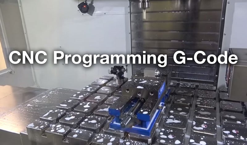
G-code is a programming language for CNC machines. It is generally called G instruction. We use this language to tell a machine what to do or how to do something. Using G code can realize fast positioning, anti circle interpolation, along circle interpolation, middle point arc interpolation, radius programming and jump machining. In case of a machine tool such as lathe or mill, the cutting tool is driven by these commands to follow a specific toolpath, cutting away material in order to get the desired shape.
Similarly, in case of additive manufacturing or 3D printers, the G-code commands instruct the machine to deposit material, layer upon layer, forming a precise geometric shape.
Check out the list of G-codes in CNC machining.
G00 – Rapid positioning
G01 – Linear interpolation
G02 – Circular interpolation clockwise
G03 – Circular interpolation counterclockwise
G04 – Dwell
G05 – High-precision contour control
G06 – Parabolic interpolation
G08 – Feed acceleration
G09 – Feed deceleration
G10 – Programmable data input
G17 – XY plane selection
G18 – ZX plane selection
G19 – YZ plane selection
G20 – Programming in inches
G21 – Programming in millimeters
G22 – Radius dimension programming method
G220 – Use on the system operation interface
G23 – Diameter size programming method
G28 – Return home
G30 – Magnification cancellation
G31- Definition of magnification
G34 – Increased pitch thread cutting
G35 – Reduced pitch thread cutting
G40 – Cutter compensation cancel
G41- Cutter compensation left
G42 – Cutter compensation right
G43 – Tool length compensation + direction
G44 – Tool length compensation – direction
G45 – Axis offset single increase
G46 – Axis offset single decrease
G47 – Axis offset double increase
G54 – Workpiece coordinate system 1 selection
G55 – Workpiece coordinate system 2 selection
G56 – Workpiece coordinate system 3 selection
G57 – Workpiece coordinate system 4 selection
G58 – Workpiece coordinate system 5 selection
G59 – Workpiece coordinate system 6 selection
G74- Back to reference point
G75 – Return to the zero point of programming coordinates
G76 – Threading compound cycle
G80 – Canned cycle cancel
G81- External canned cycle
G331 – Thread canned cycle
G90 – Absolute command
G91 – Absolute command
G96 – Constant line speed control
G97 – Cancel constant line speed control
G00 – Rapid positioning
Format: G00 x (U)__ Z(W)__
Explain:
(1) The command makes the tool move to the designated position quickly according to the point control mode. The workpiece shall not be machined during moving.
(2) All programming axes move at the speed defined by the parameters at the same time. When one axis finishes the programming value, it stops, while other axes continue to move. If you want to learn UG programming, you can get learning materials in QQ group 1006319362.
(3) There is no need to program the coordinates that do not move.
(4) G00 can be written as G0.
G01 – Linear interpolation
Format: G01 x (U)__ Z(W)__ F__ (mm/min)
Explain:
(1) The command makes the tool move to the specified position according to the linear interpolation mode. The moving speed is the feed speed instructed by F. All coordinates can be linked.
(2) G01 can also be written as G1.
Example: G01 X40 z20 F150, two axis linkage from point a to point B
G02 – Circular interpolation clockwise
Format 1: G02X(u)____ Z(w)____ I____ K____ F_____
Explain:
(1) When x and Z are at G90, the coordinates of arc end point are absolute coordinates relative to the programming zero point. In G91, the end point of the arc is the increment value relative to the start point of the arc. Regardless of G90 and G91, I and K are the incremental coordinates of the center of the arc relative to the starting point. I is the value in X direction and K is the value in Z direction. The coordinates of the center of a circle should not be omitted in circular interpolation, unless it is programmed in other formats.
(2) G02 instruction programming, you can directly over the quadrant circle, round and so on.
(3) G02 can also be written as G2.
Example: G02 X60 Z50 i40 K0 F120
Format 2: g02x (U)____ Z(w)____ R(+-)__ F__
Explain:
(1) It can’t be used to program the whole circle
(2) R is the radius of one side r arc of the workpiece. R is signed, “+” means that the arc angle is less than 180 degrees; “-” means that the arc angle is greater than 180 degrees. Where “+” can be omitted.
(3) When the length between the end point and the starting point is greater than 2R, the arc is replaced by a straight line.
G04 – Dwell
Format: G04__ F__ Or G04__ K__
Explain: The processing motion is suspended, and the processing will continue when the time is up. The pause time is specified by the data after F. The unit is seconds. The range is 0.01 seconds to 300 seconds.
G05 – Middle point arc interpolation
Format: g05x (U)____ Z(w)____ IX_____ IZ_____ F_____
Explain:
(1) x and Z are the coordinates of the end point, IX and iz are the coordinates of the middle point. Others are similar to G02 / G03.
Example: G05 X60 Z50 ix50 iz60 F120
G08 – Acceleration / deceleration
Format: G08
Explain:
They occupy a single line in the program segment. When the program runs to this segment, the feed speed will increase by 10%. If it needs to increase by 20%, it needs to be written as two separate segments.
G22 – Radius programming
Format: G22
Explain:
If you occupy a single line in the program, the system will run in the way of radius, and the following values in the program are also based on the radius.
G23 (G230) – Diameter dimension programming mode
Format: G23
Explain:
If you occupy a single line in the program, the system runs in diameter mode, and the following values in the program are also based on the diameter.
G25 – Jump processing
Format: G25 LXXX
Explain:
When the program is executed to this section of the program, it will transfer the specified section. (XXX is the program segment number).
G26 – Cycle processing
Format: g26 LXXX QXX
Explain:
When the program is executed to this section of the program, it specifies that the program section starts to this section as a loop body, and the number of cycles is determined by the value after Q.
G30 – Rate cancellation
Format: G30
Explain:
In the program alone occupy a line, with G31 use, cancel G31 function.
G31/32/33 – Definition of magnification
Format: G31 F_____
G32 – equal pitch thread processing (English system)
G33 – equal pitch thread processing (metric system)
Format: G32 / G33 x (U)____ Z(w)____ F____
Explain:
(1) X and Z are the coordinates of the end point, and F is the pitch
(2) G33 / G32 can only process single tool and single thread.
(3) With the change of x value, the taper thread can be machined
(4) When using the command, the spindle speed should not be too high, otherwise the tool wear is large.
G74 – Return to reference point
Format: G74 x Z
Explain:
(1) The coordinates appearing after G74 will return to zero by X and Z in turn.
(2) Before using G74, it must be confirmed that the machine tool is equipped with reference point switch.
(3) Single axis zero return can also be performed.
G81 outer circle (inner circle) fixed cycle
Format: g81__ X(U)__ Z(W)__ R__ I__ K__ F__
Explain:
(1) X and Z are the coordinate values of the end point, u and W are the increment values of the end point relative to the current point.
(2) R is the diameter of the starting section to be machined.
(3) I is rough turning feed, K is finish turning feed, I and K are signed numbers, and their symbols should be the same. The symbol convention is as follows: cutting from the outer central axis (turning the outer circle) is “-“, and vice versa is “+”.
(4) Different x, Z and R determine different switches of the outer circle, such as taper or no taper, forward taper or reverse taper, left cutting or right cutting, etc.
(5) F is the cutting speed (mm / min).
(6) After machining, the tool stops at the end point.
 Haas G Codes & M Codes List for CNC Lathe and Mill – Haas & Fanuc G-Code and M-Code PDF Download| CNCLATHING
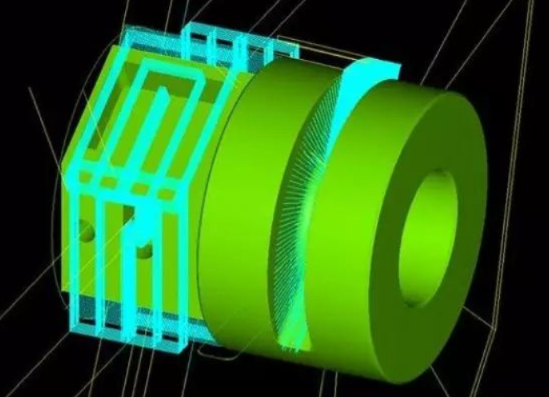 Introduction to G-Code and M-Code in CNC Programming | G-Codes & M-Codes for CNC Turning & Milling | CNCLATHING
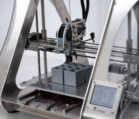 G-Code Vs M-Code: What is the Difference Between G Code and M Code in CNC Programming
 CNC Lathe Programming Guide & Tips – How to Make CNC Turning Program | CNCLATHING
 How To Find The Center Coordinates Of The Circle For CNC Machining Center – Provisions On Coordinate Axes of CNC Machine
 CNC Machining Center Vs CNC Mill – Difference Between Machining Center And Milling Machine In Programming
