
In the world of robotics, precision is paramount. Custom sheet metal components serve as the cornerstone of robotic systems, forming enclosures, brackets, and intricate support assemblies that demand durability, accuracy, and adaptability. By integrating sheet metal fabrication with CNC (Computer Numerical Control) machining, manufacturers can achieve unparalleled precision, producing components with complex geometries, tight tolerances, and superior repeatability. This article explores the advantages, processes, and cost considerations of crafting robotic components using sheet metal and CNC machining.

What’s Sheet Metal?
Sheet metal is a thin, flat piece of metal that is formed through industrial processes and is widely used in manufacturing and construction. It is typically made from materials such as steel, aluminum, brass, copper, or titanium, and can vary in thickness, ranging from very thin sheets (called foil) to thicker plates. Sheet metal is valued for its versatility, as it can be cut, bent, and shaped into various forms using specialized tools and techniques, making it essential for applications like automotive panels, appliances, roofing, HVAC systems, aerospace components, and more.
Why Choose Sheet Metal for Robotic Components
Sheet metal is an excellent choice for robotic components due to its versatility, strength, and lightweight properties. It provides the structural integrity necessary to withstand stresses while maintaining a low weight, which is crucial for optimizing the efficiency and mobility of robotic systems. The material’s ease of fabrication allows for precise cutting, bending, and shaping, enabling the creation of custom designs that meet the specific requirements of robotic applications. Additionally, sheet metal offers excellent durability and resistance to environmental factors such as corrosion, ensuring the longevity of robotic components. Its cost-effectiveness and adaptability to mass production further make it an ideal material for building reliable and high-performance robotic systems.
What Sheet Metal Alloys Are Best For Robots?
The choice of sheet metal alloys for robots depends on the specific requirements of the application, such as strength, weight, corrosion resistance, and cost. Here are some of the best sheet metal alloys commonly used for robotic components:
Aluminum Alloys
Alloy 6061: Known for its excellent strength-to-weight ratio, corrosion resistance, and ease of fabrication. Ideal for lightweight robotic arms and structural components.
Alloy 5052: Offers superior corrosion resistance, making it suitable for robots operating in harsh or marine environments.
Stainless Steel Alloys
Grade 304: Widely used for its strength, corrosion resistance, and affordability. Suitable for robotic enclosures or components exposed to moisture or chemicals.
Grade 316: Provides enhanced corrosion resistance, particularly in saline or corrosive environments, making it ideal for underwater robots.
Titanium Alloys
Grade 5 (Ti-6Al-4V): Combines high strength, lightweight properties, and excellent corrosion resistance. Used in high-performance or aerospace robotics where weight and durability are critical.
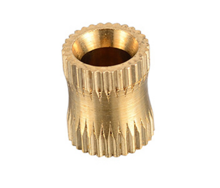
Copper Alloys
Brass or Phosphor Bronze: Often used for electrical components in robots due to their excellent conductivity and resistance to wear.
Carbon Steel
Low-Carbon Steel (Mild Steel): Cost-effective and easy to machine, suitable for non-corrosive environments or when components are painted/coated.
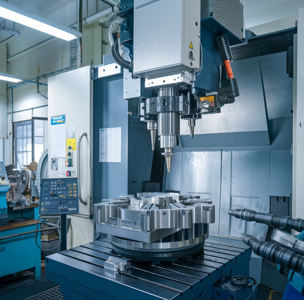
Process of Designing Robotic Components with CNC Machining
Designing robotic components with CNC (Computer Numerical Control) machining involves several steps to ensure precision, functionality, and efficiency. Below is an outline of the process:
1. Define Requirements and Specifications
Start by identifying the functional requirements of the robotic component, such as load capacity, size, weight, material, and environmental factors (e.g., temperature, corrosion resistance).
Specify tolerances, surface finishes, and mechanical properties to ensure the component meets its intended purpose.
2. Create a 3D CAD Model
Use Computer-Aided Design (CAD) software (e.g., SolidWorks, Fusion 360) to create a detailed 3D model of the component.
Incorporate features like holes, slots, or pockets necessary for assembly and functionality.
Optimize the design for manufacturability, minimizing complex geometries that could increase machining time and cost.
3. Select the Material
Choose a material based on the component’s requirements (e.g., aluminum for lightweight parts, stainless steel for durability, or titanium for high strength).
Consider factors like machinability, cost, and availability of the material.
4. Perform Structural Analysis
Use simulation tools (e.g., FEA – Finite Element Analysis) to evaluate the strength, durability, and performance of the design under expected loads and conditions.
Make design adjustments to address weak points or optimize weight without compromising strength.
5. Convert CAD to CAM
Import the 3D CAD model into CAM (Computer-Aided Manufacturing) software (e.g., Mastercam, Autodesk Fusion 360).
Generate toolpaths for CNC machines, specifying cutting tools, speeds, feeds, and machining strategies (e.g., milling, drilling, turning).
6. Prototype and Test
Create a prototype of the component using CNC machining to validate the design.
Test the prototype for fit, functionality, and performance within the robotic system.
Identify any necessary design modifications based on testing results.
7. Optimize for Production
Adjust the CAD and CAM files for mass production, focusing on reducing machining time and material waste.
Standardize features and tolerances to improve repeatability in high-volume manufacturing.
8. Manufacture the Final Component
Set up the CNC machine with the finalized CAM program and ensure proper calibration.
Perform machining operations (e.g., roughing, finishing, drilling) to produce the component.
Conduct quality control checks, such as dimensional inspection and surface finish evaluation, to ensure the component meets specifications.
9. Post-Processing
Apply any required post-machining treatments, such as deburring, anodizing, polishing, or coating, to enhance durability, aesthetics, or corrosion resistance.
10. Assembly and Integration
Assemble the machined component with other parts of the robot.
Perform system-level tests to ensure compatibility and optimal performance within the robotic application.

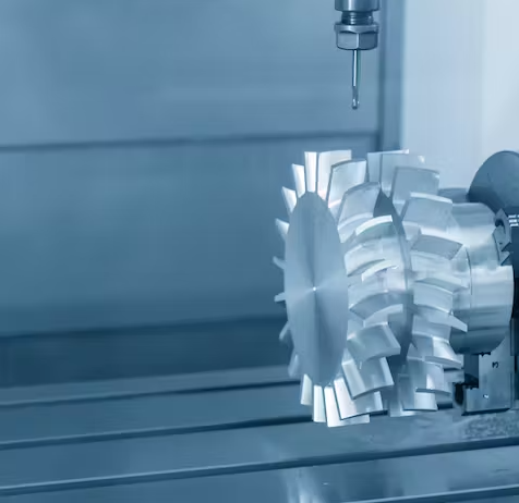
How To Select Appropriate Cutting Tools?
Selecting the appropriate cutting tools for CNC machining is a critical step in ensuring precision, efficiency, and quality when producing robotic components. The right cutting tools depend on factors such as the material being machined, the complexity of the design, and the type of machining operations required. Here’s a detailed breakdown:
1. Material of the Workpiece
The material being machined greatly influences the choice of cutting tools:
Aluminum: Use carbide tools due to their durability and ability to handle high speeds. Tools should have a polished finish or coatings like TiN (Titanium Nitride) to reduce material adhesion and improve chip evacuation.
Steel (Carbon or Stainless): High-Speed Steel (HSS) or carbide tools are suitable. For harder steels, tools with coatings like TiAlN (Titanium Aluminum Nitride) or TiCN (Titanium Carbonitride) provide heat resistance and reduce wear.
Titanium: Use carbide tools with sharp cutting edges to minimize heat generation. Avoid aggressive cuts to prevent tool wear since titanium is prone to work hardening.
Plastics or Composites: Use uncoated carbide tools with sharp edges to avoid melting or fraying. For composites, diamond-coated tools are recommended to prevent delamination.
2. Type of Machining Operation
Different operations require specific tools:
Milling:
End Mills: Flat end mills for cutting flat surfaces or slots= Ball end mills for curved or contoured surfaces. Corner radius end mills for reducing stress concentrations in corners.
Face Mills: For machining large, flat surfaces efficiently.
Roughing End Mills: For removing large amounts of material quickly, with serrated edges to reduce cutting forces.
Drilling:
Use twist drills for standard holes. For precision holes, use reamers or specialized carbide drill bits. Consider center drills for starting holes to prevent wandering.
Turning:
Use indexable carbide inserts for lathes, selecting geometries suitable for the material (e.g., positive rake for softer materials, negative rake for harder ones).
Threading:
Use taps or thread mills depending on whether internal or external threads are needed.
3. Tool Geometry
Tool geometry plays a crucial role in machining performance:
Flute Count:
Use 2-flute or 3-flute tools for softer materials like aluminum to improve chip evacuation. Use 4-flute or higher tools for harder materials like steel to achieve a smoother finish.
Helix Angle:
Higher helix angles (40°–60°) improve chip removal and surface finish but may weaken the tool. Lower helix angles (15°–30°) provide better strength for aggressive cuts in harder materials.
Cutting Edge:
Sharp cutting edges reduce cutting forces and heat generation, ideal for softer materials. Reinforced or chamfered edges increase durability for hard materials.
4. Tool Material
The material of the cutting tool determines its durability and performance:
High-Speed Steel (HSS):
Cost-effective and versatile, suitable for general-purpose machining. Best for softer materials and lower-speed applications.
Carbide:
Offers higher hardness and heat resistance, making it ideal for high-speed machining and hard materials. More brittle than HSS, requiring careful handling.
Cermet or Ceramic:
Excellent for high-speed finishing operations on hard materials like steel. Not suitable for interrupted cuts due to brittleness.
Diamond-Coated Tools:
Ideal for non-metallic materials like composites, graphite, and ceramics. Not recommended for ferrous metals, as they can degrade the diamond coating.
5. Tool Coatings
Tool coatings enhance performance by improving wear resistance, heat resistance, and lubricity:
TiN (Titanium Nitride):
Improves tool life and reduces friction. Suitable for general-purpose machining.
TiAlN (Titanium Aluminum Nitride):
Increases heat resistance, ideal for machining hard materials at high speeds.
DLC (Diamond-Like Carbon):
Best for machining non-ferrous metals and plastics.
ZrN (Zirconium Nitride):
Offers excellent lubricity, reducing material buildup on tools when machining aluminum.
6. Machine Parameters and Cutting Speeds
The cutting tool must match the capabilities of the CNC machine and the selected parameters:
Spindle Speed (RPM):
Ensure the tool can handle the operating speeds without overheating or breaking.
Feed Rate:
Select tools designed for the required feed rates to avoid chipping or tool wear.
Depth of Cut:
Use sturdy tools for deeper cuts to prevent deflection or vibrations.
Use high-quality tool holders to ensure proper alignment and minimize runout.
7. Tool Holder and Stability
For long-reach applications, use tools with rigid shanks to prevent deflection.
Custom Robotic Components Price, Is It Expensive?
The price of custom robotic components made from sheet metal using CNC machining depends on several factors, including material, complexity, machining time, quantity, and post-processing. Common materials like aluminum cost $3–$6 per pound, while stainless steel and titanium are more expensive, at $5–$15 and $25–$50 per pound, respectively. CNC machining rates range from $50 to $150 per hour, with complex or multi-axis designs increasing costs due to longer machining times. Single prototypes or small batches can cost $200–$1000 per part, while larger quantities benefit from economies of scale, significantly reducing unit costs. Additional post-processing, such as anodizing or powder coating, can add $50–$200 per batch, further influencing the final price.

Related Articles:
 Spring Material Types (Properties, Grades, Uses) & Best Selection for Your Project
 Why Choose China CNC Machining and How to Find the Best CNC Machining Manufacturer
 CNC Machining Vs Conventional Machining – Difference Between CNC Machining And Conventional Machining
 What Are Configuration Requirements For High-Speed CNC Machining
 CNC Machining VS Manual Machining: What is the Difference Between CNC and Manual Machining
 What is HVOF Coating – HVOF Thermal Spray Process, Materials, Benefits, Machine, Applications