
GD&T is a powerful system for defining and controlling the shape, size, location, and orientation of features on manufactured parts. Within this system, angularity stands out as a crucial control for specifying the orientation of a surface or axis relative to a datum. This article talks about GD&T angularity, exploring its definition, application, symbol, callout, tolerance zone, measurement, and differences from other GD&T symbols like profile.
GD&T Angularity Definition – What Is Angularity in GD&T?
Angularity in GD&T (Geometric Dimensioning and Tolerancing) is a type of orientation control that ensures a part feature, like a surface or a hole, is positioned at a specific angle relative to a reference surface or datum. Instead of directly telling how much the angle can vary, angularity defines a tolerance zone, usually between two parallel planes or surfaces that are tilted at the desired angle. The feature’s axis, surface, or center plane must stay within this zone to meet the design requirements. This control is important for parts with angled surfaces or holes that need to fit precisely with other components, helping maintain the correct tilt so everything assembles properly. Angularity can also control the direction of non-circular features like slots or tabs by keeping them within a set angular tolerance zone. In essence, it helps keep parts aligned at the right angle, ensuring machines work smoothly and parts fit together as intended.
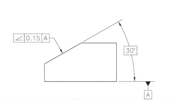
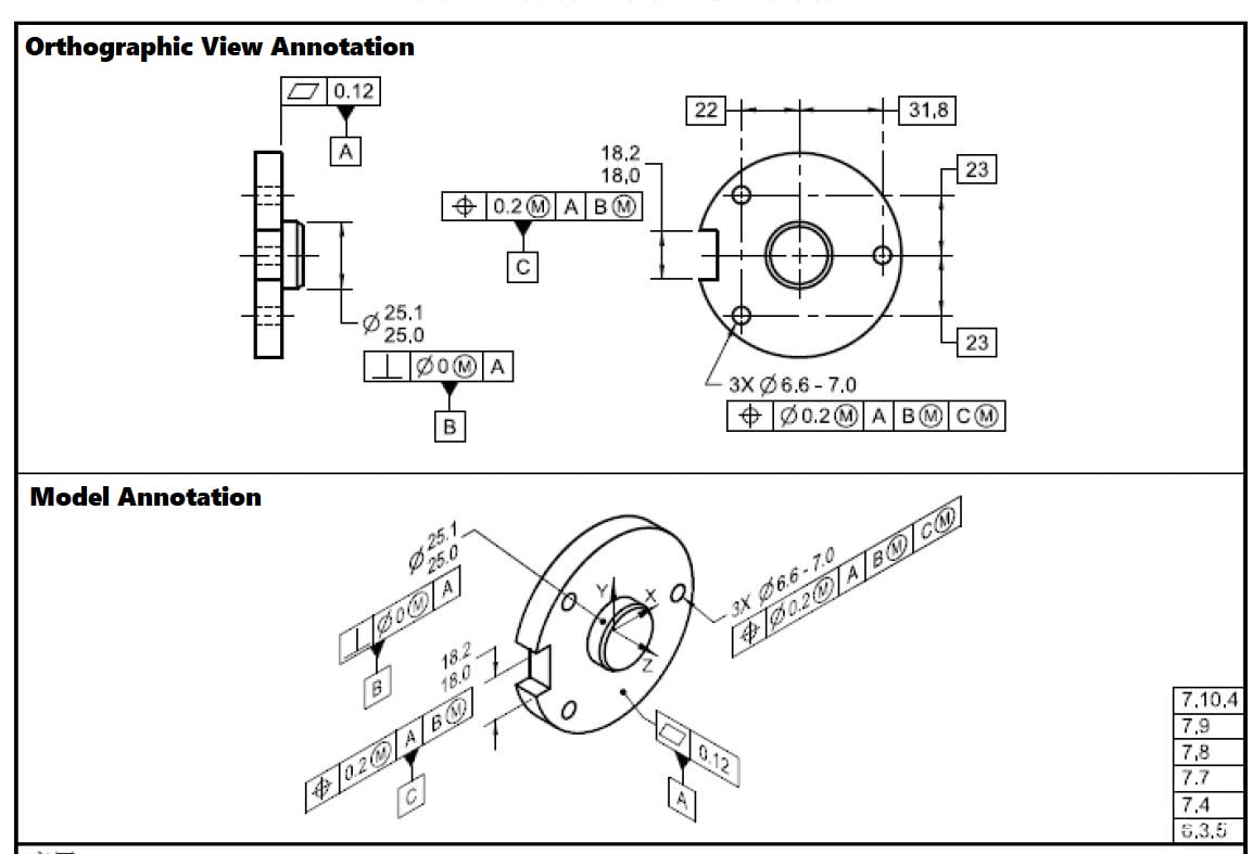
GD&T angularity can also be applied and visualized in a 3D model, where the nominal angle (such as 30°) is given as a basic dimension, and the datum feature is clearly referenced. Unlike typical angle measurements, the tolerance units for angularity are not degrees but linear units like millimeters or inches. This is because angularity defines a tolerance zone formed by two parallel planes set at the nominal angle, separated by a specified linear distance. The feature’s surface or axis must lie entirely within this zone, which limits how far it can deviate from the perfect angular position at any point.
GD&T Angularity Symbol & Callout
The symbol for angularity is an angled triangle (∠) placed next to the tolerance value in the feature control frame.
Angularity Drawing Callout:
GD&T Angularity Tolerance Zone
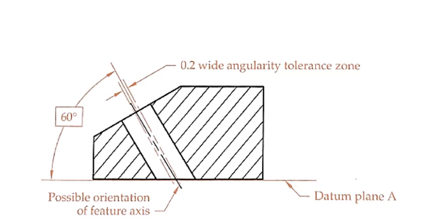
The angularity tolerance zone is a geometric control that specifies how much an angled surface or axis can deviate from its theoretical (basic) angle relative to a datum reference. The tolerance zone of GD&T angularity can be either two parallel lines, specified without the Ø symbol, creating a 2D tolerance zone where the controlled surface must lie between two parallel lines spaced apart by the tolerance value, or a cylindrical zone, specified with the Ø symbol, creating a 3D cylindrical boundary within which the axis or centerline of the feature must lie, with the cylinder’s diameter equal to the tolerance value. The tolerance is presented by linear distance units.
Key Components:
- Basic Angle: When specifying angularity tolerance, the nominal angle must be shown as a basic dimension (typically shown in a box □ or without tolerances), and general tolerances from the title block or notes do not apply to this dimension. It represents the theoretical exact angle from which deviation is controlled.
- Datum Reference: An angularity tolerance must always reference at least one datum, which serves as the geometric reference from which the specified angle is measured. This datum is typically a flat surface, centerline, or axis that establishes the orientation basis for the angular feature.
How to Measure GD&T Angularity?
Measuring GD&T angularity involves ensuring that a feature is oriented at a specified angle relative to a datum.
1. Sine Bar Method:
- Setup: Place the part on a sine bar that is set to the required angle. The sine bar allows the part to be tilted to the specified angle while keeping the reference surface horizontal.
- Measurement: Use a dial gauge to measure the flatness of the surface that is now horizontal. The entire surface must lie within the defined tolerance zone.
2. Coordinate Measuring Machine (CMM):
- Setup: Position the part in the CMM, which can measure the angle and flatness simultaneously.
- Measurement: The CMM will provide precise data on the surface’s orientation relative to the datum, ensuring that all points on the surface fall within the tolerance zone.
3. Optical Comparator:
- Setup: Use an optical comparator to project the part’s profile onto a screen.
- Measurement: Compare the projected image against the specified angle and tolerance zone. This method is useful for visual inspection and verification.
4. Go/No-Go Gauges:
- Setup: For high-volume production, custom gauges can be designed to check if the part falls within the acceptable tolerance zone.
- Measurement: These gauges provide a quick pass/fail assessment based on the angularity specifications.
Note:
- Datum Reference: Angularity must always be measured relative to a datum. The datum establishes the reference angle, and any changes to the datum can affect the measurement outcome.
- Tolerance Zone: The tolerance zone for angularity is not defined in angular units (degrees or radians) but rather as a linear distance between the two parallel planes or the diameter of the cylindrical zone.
- Flatness Control: Angularity also implies a control over flatness. The surface must not only be at the correct angle but also flat within the specified tolerance.
GD&T Angularity vs Profile
In GD&T, there are profile of a surface and profile of a line.
1. What They Control and Measure
- Profile of a Surface controls the shape of a whole 3D surface. It makes sure every single point on a curved or complex surface stays inside a special 3D zone that matches the designed shape. Imagine wrapping the surface with two invisible “parallel” layers, and the real surface can’t go outside those layers.
- Profile of a Line focuses only on a 2D slice or cross-section of a shape. It checks how much a single line or curve can wiggle away from the perfect shape at that specific cut. This means it controls only one slice at a time, not the whole surface.
- Angularity is different because it controls the angle between one feature and a reference feature (called a datum). Instead of controlling shape or form, it controls how a surface or line is tilted or slanted relative to another surface. The angle itself is fixed and considered “basic,” and the tolerance controls how much the surface can shift within two parallel planes set at that angle.
2. Dimensionality and Tolerance Zones
- Profile of a Surface uses a 3D tolerance zone, two parallel surfaces that follow the shape of the real surface, enclosing it in space. This means the entire surface must fit inside this zone.
- Profile of a Line uses a 2D tolerance zone, two parallel curves that follow the shape of just one cross-section line. Only that slice of the surface is checked, not the whole thing.Angularity uses two parallel planes or lines set at a specific angle to a datum. The surface or line must lie entirely within this angled zone, controlling orientation but not the exact angle variation.
3. Relation to Datum and Measurement Methods
- Angularity always references a datum (a specific feature used as a starting point). It’s about the relationship between the angled feature and the datum, often checked with special tools like a sine bar that tilts the part to the right angle to measure flatness along the tilted surface.
- Profile of a Surface may or may not be referenced to a datum, depending on the drawing. It’s usually measured with a Coordinate Measuring Machine (CMM) that scans the whole surface and compares it to the perfect shape.
- Profile of a Line can also be with or without a datum, and it is measured at specific cross-sections, often using a CMM or specialized gauges to measure how closely the line matches the intended curve.
4. Application and When to Use
- Profile of a Surface is the go-to symbol when you need to control complex 3D shapes that curve in multiple directions, like car hoods or airplane wings, ensuring every point fits inside the tolerance zone.
- Profile of a Line is used when only certain cross-sections of a shape need control, for example, checking the shape of a curved edge or radius at several locations along a part.
- Angularity is used to control the tilt or slant of a surface or feature relative to another, such as making sure a bent part hooks correctly at a specific angle, without directly controlling the angle dimension, but controlling the surface’s position within a zone.
5. Relation to Other GD&T Symbols
- Angularity is part of the orientation group, closely related to perpendicularity and parallelism, which are special cases of angularity at 90° and 0°, respectively.
- Profile of a Line relates to straightness and circularity because all deal with how much a line or curve can vary in 2D.
- Profile of a Surface is like the 3D version of the profile of a line and can also combine orientation, size, and location controls when used with datums, making it the most versatile surface control symbol.
| Difference | Profile of a Surface | Profile of a Line | Angularity |
|---|---|---|---|
| Controls | The entire 3D surface shape | 2D cross-section line shape | Orientation angle of feature |
| Tolerance Zone | 3D zone (two parallel surfaces) | 2D zone (two parallel curves) | Two parallel planes at an angle |
| Dimension Reference | Optional datum | Optional datum | Always referenced to a datum |
| Measurement Tool | CMM or height gauge | CMM or profile gauge | Sine bar, angle setup |
| Application | Complex curves (wings, hoods) | Specific cross-sections | Tilt or slant relative to the datum |
| Relation to Other Symbols | General surface control combines form, size, and location | Similar to straightness, circularity | Related to perpendicularity, parallelism (orientation group) |
| Angle Control | No direct angle control | No direct angle control | Controls position within the angled zone, not the angle itself |
| Uses | Whole curved surface tolerance | Radius or edge curve profile | Bent feature at a fixed angle |
Related Articles:
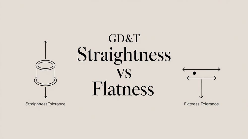 Straightness vs Flatness – Difference Between Flatness and Straightness
 GD&T Profile Tolerance: Basic Knowledge, Types, Symbol, Calculation, Uses
 GD&T MMC: Definition, Formula, Calculation, Bonus Tolerance, Uses, MMC vs LMC
 GD&T Tolerance Definitions: 14 Different Tolerances Specific to GD&T Use
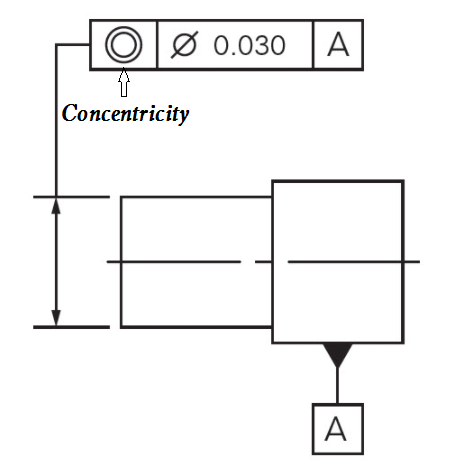 What is Concentricity in GD&T – How to Measure, Calculate Concentricity & Concentricity vs Runout
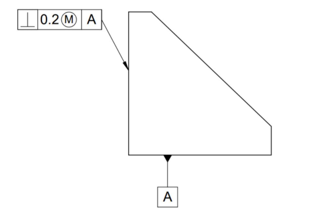 GD&T Perpendicularity Definition, Symbol, Measurement & Perpendicularity vs Squareness