Geometric tolerances are critical for ensuring accuracy and precision in manufactured parts. One important type of geometric tolerance is profile tolerance, which regulates the form of curves, curved surfaces, and other non-flat features. This article provides an in-depth look at profile tolerance, explaining the different types, how to properly indicate profile tolerance on drawings, and examples of using profile tolerance as both a form tolerance and positional tolerance. For those unsure of how to utilize profile tolerances, this guide serves as a helpful reference for properly specifying and interpreting profile tolerance symbols, datum references, and tolerance values on drawings and blueprints. Read on to gain a clearer understanding of the meaning, measuring, and application of profile tolerances.
What is Profile Tolerance?
Profile tolerance also known as contour tolerance is a geometric tolerance that is used when you want curves or curved surfaces (curves and curved surfaces) to be produced accurately. A characteristic is that it can also be used as a form tolerance, orientation tolerance (*), or positional tolerance. When used as an orientation tolerance or positional tolerance, it is necessary to specify a datum.
(*) Since the opportunity to use it as an orientation tolerance is rare, this article will only introduce how to use it as a form tolerance and positional tolerance.
Types of Profile Tolerance
There are two types of profile tolerance:
- Line profile
What is line profile?
“Line profile” is a geometric tolerance that is indicated to a shape to indicate the desired curve.
The shape that can be regulated by line profile is a single free curve on the specified surface, and the area between the two curves sandwiching it becomes the tolerance zone.
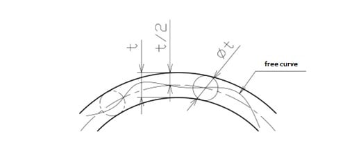
(1) Using line profile as a form tolerance
First, how to use line profile as a “form tolerance” will be explained:
① Indication of line profile on the upper surface of a part
Considering a part with a curved surface on the upper surface. Assuming that the curve shape on the upper surface is required to be accurate and the deviation from the ideal shape is acceptable within 0.05mm (width 0.1mm) from the center.
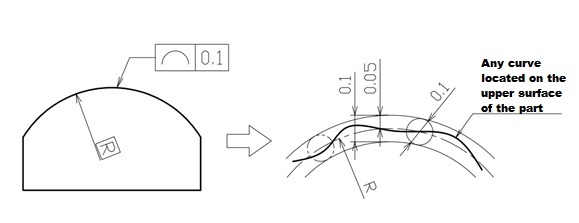
In this case, any single curve located at an arbitrary position on the surface is the regulated object. Therefore, as shown in the above picture, indicate the line profile away from the dimensional line indicating the profile on the upper surface.
Also, when using a line profile, use a “theoretically accurate dimension (hereinafter referred to as theoretical dimension)” indicating the ideal curve. Therefore, the dimension indicating the profile needs to be enclosed by a square. Since the tolerance zone is an area obtained by equally dividing the tolerance value from the theoretical dimension at the center, φ is not attached before the tolerance value.
②Indication of line profile for the entire circumference of a part
Then, what if you want to regulate the line for the entire circumference of the part, including the upper surface, in the same case of a part with a curved surface on the upper surface?
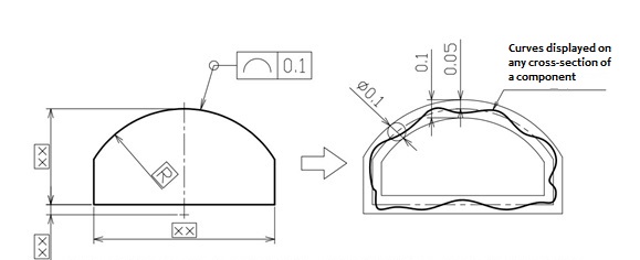
In this case, as shown in the above picture, enclose the bent portion where the lead line is connected to the tolerance frame with a circle. This is the symbol indicating entire circumference indication. Also, the dimension indicating the shape needs to be enclosed by a square as usual.
(2) Using line profile as a positional tolerance
Next, how to use line profile as a positional tolerance will be explained:
When used as a positional tolerance, in addition to regulating the intended curve shape of the designer, the position of that curve is also regulated.
① When indicated based on a plane as a reference for the upper surface of a part
Assuming that you want an accurate curve in an exact position from a reference surface according to the theoretical dimension. The deviation from the target curve is assumed to be acceptable within 0.05mm from the center of the theoretical dimension.
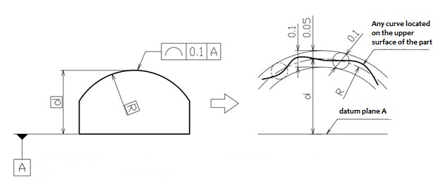
In this case, as shown in the above picture, specify a datum to the reference surface and indicate the line profile on the upper surface being regulated away from the dimensional line indicating the profile. Since they are theoretical dimensions, enclose the dimensional line and dimensional line indicating the position with a square.
- Surface Profile
What is surface profile?
“Surface profile” is a geometric tolerance that is indicated to a shape to indicate the desired curved surface.
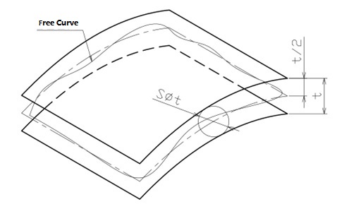
The shape that can be regulated by surface profile is a single free curved surface, and the area between the two curved surfaces sandwiching it becomes the tolerance zone, as shown in this picture:
(1) Using surface profile as a form tolerance
First, how to use surface profile as a “form tolerance” will be explained:
① Indication of surface profile on the upper surface of a part
For a part with a curved surface on the upper surface, assuming that an accurate curved surface is desired. The deviation from the ideal curved surface is assumed to be acceptable within 0.05mm from the center of the theoretical dimension.
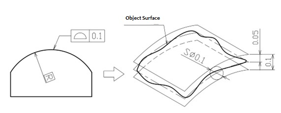
In this case, as shown in the above picture, indicate the surface profile away from the dimensional line indicating the profile on the regulated upper surface. Enclose the dimensional line indicating the profile with a square since it is a theoretical dimension. As with line profile, the tolerance zone is an area obtained by equally dividing the tolerance value from the theoretical dimension at the center, so φ is not attached before the tolerance value.
②Indication of surface profile for the entire circumference
Also, like line profile, surface profile can be applied to the entire circumference of a part.
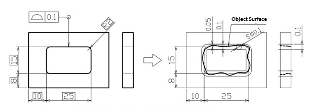
The above picture assumes a case where you want an accurate curved surface for the surface of the hole with a square hole in the center of the plate part throughout the entire circumference. The deviation from the ideal curved surface is assumed to be acceptable within 0.05mm from the center of the theoretical dimension.
In this case, indicate the surface profile on the regulated hole surface away from the dimensional line indicating the profile. Enclose the dimensional line indicating the profile with a square. Attach the symbol for entire circumference indication to the bent portion of the lead line since it regulates the entire surface circumference.
(2) Using surface profile as a positional tolerance
Next, how to use surface profile as a positional tolerance will be explained:
① Indication of surface profile on the upper surface of a part based on a plane as a reference
Assuming you want an accurate curved surface in an exact position according to the theoretical dimension from a certain reference surface. The deviation from the ideal curved surface is assumed to be acceptable within 0.05mm from the center of the theoretical dimension.
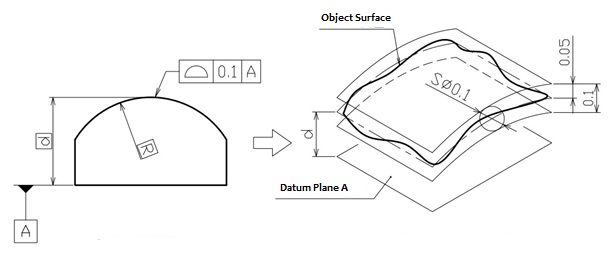
In this case, as shown in the above picture, specify a datum to the reference surface, and indicate the surface profile on the regulated upper surface away from the dimensional line indicating the profile. Enclose the dimensional line indicating the profile with a square since it is a theoretical dimension.
②Indication of surface profile for the entire circumference when the attitude or position also needs to be regulated
The indication of surface profile for the entire circumference only regulates the shape of the hole in the plate part but does not regulate the position. In this case, if you also want the hole surface to be in the exact position, it is good to specify datum planes A, B, and C.
Profile Tolerance Symbol
Here are the common symbols used for profile tolerance:
- Line profile tolerance symbol: ǻ
- Surface profile tolerance symbol: Ȝ
These symbols are placed next to the profile tolerance value on drawings and blueprints.
Some key points about profile tolerance symbols:
- ǻ is used for profile tolerance of a line or curve. It is placed next to linear profile tolerance values.
- Ȝ is used for profile tolerance of a surface. It is placed next to surface profile tolerance values.
- The symbols are abbreviations of the actual words – ǻ stands for “delta” which represents difference, and Ȝ stands for “lambda” which represents wavelength.
- They help identify at a glance that the tolerance is for a profile rather than another geometric characteristic like size, form, orientation, etc.
The profile tolerance symbol is followed by the theoretical datum indicated by the profile tolerance and then the tolerance value.
For example:
ȜA = 0.05mm
Here, Ȝ indicates it is a surface profile tolerance. A is the theoretical datum plane, and 0.05mm is the tolerance value.
Profile Tolerance Calculation: How to Measure Profile Tolerance
Here are the main methods used to measure profile tolerance:
- Comparator/Profile Projector: A comparator or profile projector is used to project the actual profile onto a drawing or other reference plane. The tolerance envelope defined on the drawing is superimposed and any gaps or overlap measured.
- Coordinate Measuring Machine (CMM): A CMM can digitally scan the actual profile and compare it to the nominal or theoretical profile defined in the CAD model. Deviations between the profiles are calculated.
- Form Testers: Specialized form testers like roundness testers, straightness testers, etc. can be used to directly measure profile parameters like circularity, straightness, flatness compared to tolerance limits.
- Stylus Probe: A CMM with a touch probe styli can trace the actual profile to build a point cloud. This is compared digitally to the specification. Deviations indicate if profile is within tolerance.
- Optical Comparator: The actual profile is viewed through an optical comparator and compared visually to a drawing or CAD image. A carl Zeiss or other optical system can facilitate comparison.
- Go/No-Go Gages: For simple nominal profiles, go/no-go plug or ring gages may be used that the part must fit within but not go beyond the tolerance zone to be considered in tolerance.
Here are the steps to calculate a profile tolerance:
- Step 1: Determine the nominal/theoretical profile shape
- This is defined on engineering drawings or CAD models. It establishes the intended ideal shape.
- Step 2: Determine the profile tolerance specification
- This includes the tolerance type (e.g. maximum material condition, least material condition), symbol (Δ or λ), datum, and tolerance value.
- Step 3: Define the tolerance zone
- For surface profile (λ), the tolerance zone is the space between two imaginary parallel surfaces that sandwich the nominal profile. For line profile (Δ), it is the space between two lines parallel to the nominal profile curve.
- Step 4: Measure the actual profile
- Use CMM, comparators, form testers etc. to obtain actual X,Y,Z coordinates along the profile.
- Step 5: Compare profiles
- Superimpose nominal and actual profiles either physically or digitally. Calculate deviations between profiles at regular intervals.
- Step 6: Calculate tolerance deviation
- The tolerance deviation is the maximum deviation between profiles within the tolerance zone.
- Compare this to the tolerance value specified. If within value, profile is dimensionally acceptable.
- Step 7: Document results
- Record all measurement data, profiles compared, maximum deviation and verification of whether profile is within tolerance limits.
The key aspects are establishing the nominal profile, defining the tolerance zone, accurately measuring deviations between profiles, and comparing the maximum deviation to the specified tolerance value. Proper application of Profile tolerances ensures dimensional performance of curved features.
Precautions When Using Profile Tolerance
Profile tolerance can be applied to almost all shapes that constitute parts, not just curves and surfaces, but also straight lines, planes, axes, and center planes. Therefore, it can also be used instead of other geometric tolerances.
However, drawings have the role of “transmission means”, so it is required to clearly convey the design intent. Also, most of the names and symbols of individual geometric tolerances directly indicate “what is being regulated”. Therefore, it is best to avoid excessive use of profile tolerance as a substitute for other geometric tolerances. Consider which geometric tolerance can clearly convey the design intent when selecting the type of tolerance.
This concludes the explanation of the basic knowledge, types, and uses of GD&T Profile Tolerance. If those with difficulty in geometric tolerances use this column as a reference, it is hoped that it will help improve design knowledge.


