
Gears are components that are applied in numerous industries, especially in automotive, aerospace, and industrial machinery. This article provides an extensive guide on gear functions, principles, manufacturing, types, classification, teeth profiles, nomenclature, and the essential calculations involved in gear design and analysis.
What Are the Functions of Gears?
Gears are mechanical components that serve several critical functions in transmitting and controlling rotational motion. They adjust rotational speed by meshing gears of different sizes, either increasing or decreasing it based on the application. Simultaneously, gears modify torque, trading off speed for rotational force to amplify or reduce it as needed. They can reverse rotational direction when meshed gears of opposite hands interact and transmit motion over distances using belts, chains, or additional gears. Gears synchronize the rotation of multiple shafts, ensuring they operate in unison or at controlled ratios. They distribute mechanical stress across multiple teeth, enhancing durability and load-bearing capacity. Precision gears minimize backlash for accurate positioning, which is crucial in robotics and machinery. Complex gear arrangements, like planetary systems, enable multiple ratios in compact designs. Even idler gears, which primarily change rotation direction without affecting speed or torque, play a role in optimizing mechanical systems.
How Do Gears Work?
Gears work through the interaction of toothed wheels or cylinders that mesh together to transmit rotational motion and force between parallel, intersecting, or non-parallel shafts. When two gears are meshed, their teeth engage, causing the rotation of one gear to drive the rotation of the other, with the direction of rotation depending on gear orientation—opposite for parallel gears and potentially the same when connected via an idler gear. The fundamental principle is based on the gear ratio, which is the ratio of the number of teeth on the driven gear to the number of teeth on the driving gear, determining how rotational speed and torque are modified. For example, a 20-tooth driving gear meshed with a 40-tooth driven gear creates a 2:1 gear ratio, resulting in the driven gear rotating at half the speed but delivering twice the torque.
How Do Gears Work in a Car?
In a car, gears work by transmitting power from the engine to the wheels while adjusting rotational speed and torque through gear ratios. The engine’s crankshaft connects to a clutch (in manual transmissions) or torque converter (in automatic transmissions), which then links to the transmission input shaft. Inside the transmission, various gear sets mesh together, with gear selection determining the ratio of input to output rotation. Lower gears (with smaller input gears driving larger output gears) provide higher torque for acceleration from rest, while higher gears (with larger input gears driving smaller output gears) allow for higher speeds with reduced engine RPM. The differential gears at the rear (or front/mid in some vehicles) further adjust the rotation to accommodate turns, allowing wheels to rotate at different speeds when necessary. Shifting gears manually or automatically changes which gear set is engaged, optimizing the balance between speed and torque for different driving conditions, from starting off to highway cruising.
Gear Manufacturing Process
The gear production processes can be divided into two broad categories.
1. Gear Forming
The forming processes in gear manufacturing involve shaping the gear through methods such as casting, sintering, injection molding, extruding, cold drawing, stamping, and forging. These techniques are primarily used to create the initial shape of the gear blank before any machining takes place. Forming processes are advantageous for producing complex shapes and can be more cost-effective for larger production runs, as they often require less material and energy compared to machining.
2. Gear Machining
Machining processes are essential for refining the gear’s dimensions and surface finish after the initial forming stage. This category includes operations such as roughing, finishing, milling, shaving, grinding, gear shaping, burnishing, lapping, and honing. Each of these methods is designed to achieve specific tolerances and surface qualities, with some processes, like lapping and honing, providing super-finishing capabilities that yield high precision and smooth surfaces critical for gear performance.
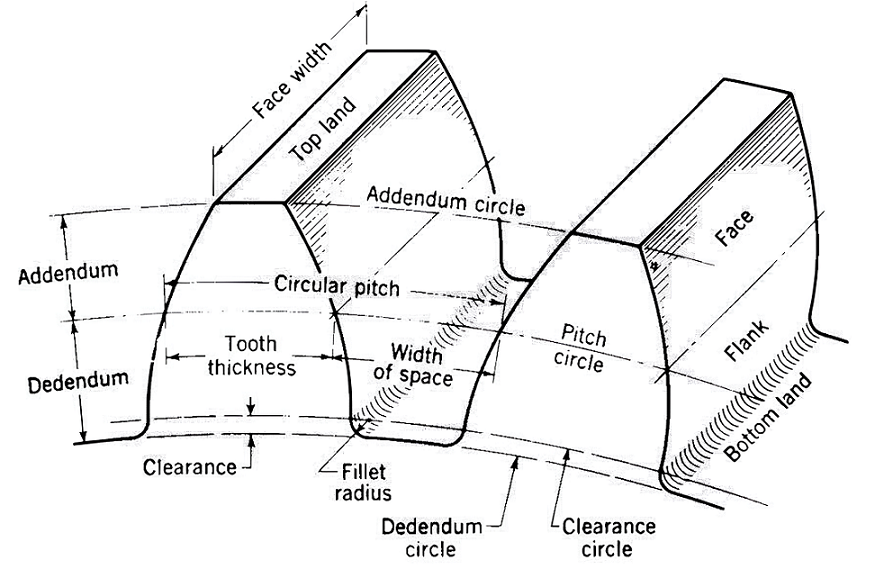
Gear Teeth Profile & Nomenclature
One of the important aspects of gear design is the profile of gear teeth. Below are definitions and calculations for key terms related to gear profiles.
Note: Diametral pitch is the number of teeth per unit length of the pitch circle diameter in inches. On metric gear drawings, the normal module is used instead of the normal diametral pitch; the normal module is calculated by dividing 25.4 by the normal diametral pitch.
1. Addendum: The height by which a tooth of a gear projects above the pitch circle.
- Formula: Addendum = 1/Diametral Pitch
2. Dedendum: The depth of the tooth from the pitch circle to the root circle. It is typically larger than the addendum to ensure that the tops of the mating gear teeth can pass without interference.
- Formula: Dedendum = 1.25/Diametral Pitch
3. Clearance: The space between the top of one gear tooth and the bottom of the mating gear tooth.
- Formula: Clearance = 0.25/Diametral Pitch
4. Fillet Radius: The small radius that connects the tooth profile to the root circle. It is important for reducing stress concentrations.
- Formula: Fillet Radius = 0.3/Diametral Pitch
5. Dedendum Circle: The circle that passes through the bottom of the teeth (root circle).
- Formula: Dedendum Circle Diameter=Pitch Circle Diameter−2×Dedendum
6. Clearance Circle: The circle that passes through the top of the mating gear teeth.
- Formula: Clearance Circle Diameter=Dedendum Circle Diameter+2×Clearance
7. Pitch Circle: An imaginary circle that represents the point of contact between two meshing gears.
- Formula: Pitch Circle Diameter= Number of Teeth/Diametral Pitch = Module x Number of Teeth
8. Tooth Thickness: The width of the tooth measured along the pitch circle.
- Formula: Tooth Thickness=1.5708/Diametral Pitch
9. Width of Space: The width between two adjacent teeth measured along the pitch circle. It is equal to the tooth thickness plus the backlash.
10. Circular Pitch: Circular pitch is the distance measured along the circumference of the pitch circle from one tooth to the corresponding point on the next tooth.
- Formula: Circular Pitch=πx Pitch Circle Diameter/Number of Teeth
11. Addendum Circle: The circle that passes through the tops of the teeth.
- Formula: Addendum Circle Diameter=Pitch Circle Diameter+2×Addendum
12. Face Width: The width of the gear tooth measured parallel to its axis. It is typically specified based on the application requirements.
Gear Ratio
A gear ratio is the relationship between the sizes of two meshed gears, specifically the ratio of the number of teeth on the driven gear to the number of teeth on the driver gear. This ratio determines the mechanical advantage of the gear system, influencing both speed and torque. For instance, in a gear train where a smaller gear (pinion) drives a larger gear, the output speed decreases while the torque increases, a mode known as “gear reduction.” Conversely, if the larger gear drives the smaller one, the output speed increases, resulting in lower torque, which is referred to as “overdrive.” When the driver and driven gears are the same size, the system operates in “direct drive,” where the torque remains constant throughout.
The gear ratio can be calculated using the formula:
- Gear Ratio = Number of Teeth on Driven Gear/Number of Teeth on Driver Gear
Gear Classification and Types
According to the position of the axes of the shafts, gears can be classified into parallel shaft, intersecting shaft, non-parallel & non-intersecting shaft categories.
Parallel-Shaft Gears
Parallel-shaft gears are characterized by having their shaft axes aligned in the same plane and parallel to each other. The teeth on these gears can either be straight (as in spur gears) or inclined (as in helical gears). This category includes various transmission arrangements, such as external gears, internal gears, and rack-and-pinion systems. The engagement of these gears typically allows for efficient power transmission due to their simple design and high mechanical efficiency.
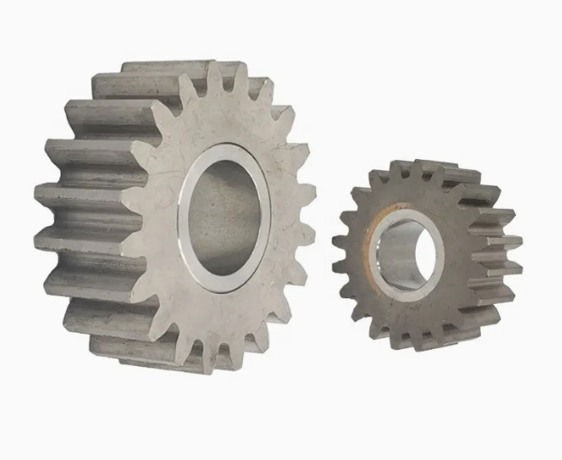
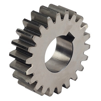
1. Spur Gear
Spur gears are the simplest and most common type of gear, featuring straight teeth aligned parallel to the shaft axis. They are designed to transmit power between parallel shafts and are widely used in various mechanical systems.
- Advantages: Simple design, easy to manufacture, high efficiency.
- Disadvantages: Noisy operation, vibration due to simultaneous tooth engagement.
- Applications: Gearboxes, conveyors, and machinery requiring low to medium speeds.
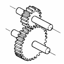
2. Helical Gear
Helical gears have teeth cut at an angle to the shaft, allowing for gradual engagement. This design results in smoother and quieter operation compared to spur gears.
- Advantages: Higher load capacity, smoother operation, reduced noise.
- Disadvantages: Thrust loads can complicate design and lead to higher manufacturing costs.
- Applications: Automotive transmissions, industrial machinery.
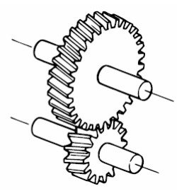
3. Herringbone Gear
Also known as double helical gears, herringbone gears consist of two helical gears with opposite orientations. This design cancels out axial thrust, providing a balanced operation.
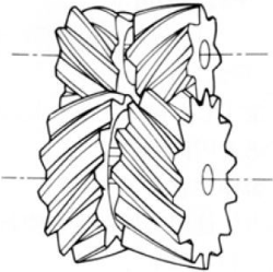
- Advantages: Eliminates thrust issues and multiple tooth engagement.
- Disadvantages: They are More complex to manufacture than spur or helical gears.
- Applications: Heavy machinery, marine applications.
4. Rack and Pinion
Rack and pinion systems convert rotary motion into linear motion. The pinion is a small gear that meshes with a linear rack.
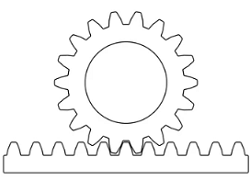
- Advantages: Effective conversion of motion, simple design.
- Disadvantages: Limited load capacity compared to other gear types.
- Applications: Steering systems in vehicles, machine tools.
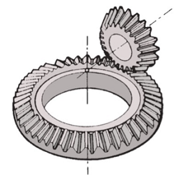
Intersecting-Shaft Gears
Intersecting-shaft gears have axes that meet at a point, typically at a right angle. This configuration is most commonly accomplished using bevel gears, which are conical in shape. A pitch cone of any other angle is simply called a bevel gear. There are two special types of bevel gears. One is crown gear, which a type of bevel gear where the pitch cone angle is 90 degrees. Miter gears are a specific type of bevel gear with equal numbers of teeth and shafts positioned at right angles to each other. They have matching pitch surfaces and conical shapes. The primary types of intersecting-shaft gears include straight bevel gears and spiral bevel gears. These gears are designed to transmit motion between axes that intersect, making them ideal for applications where space constraints require a change in direction of the rotational motion.
1. Straight Bevel Gear
Straight bevel gears have straight teeth and are used to transmit motion between shafts that are at right angles to each other.
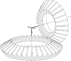
- Advantages: Simple design, cost-effective.
- Disadvantages: Limited to low-speed applications, can be noisy.
- Applications: Automotive differentials, hand tools.
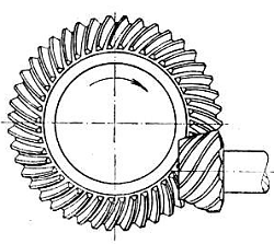
2. Spiral Bevel Gear
Spiral bevel gears feature curved teeth that provide smoother engagement and higher contact ratios.
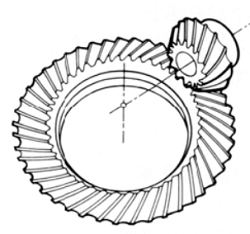
- Advantages: Quieter operation and higher efficiency than straight bevel gears.
- Disadvantages: More complex manufacturing process.
- Applications: High-speed applications, automotive gear systems.
3. Zerol Bevel Gear
Zerol bevel gears combine characteristics of both straight and spiral bevel gears. They have curved teeth like spiral bevel gears but with a zero-degree spiral angle at the middle of the face width. They replicate the characteristics of straight bevel gears while being manufactured using a spiral bevel cutting process.
- Advantages: Smooth operation, reduced thrust loads, interchangeability with straight bevel gears.
- Disadvantages: Complex manufacturing, limited load capacity compared to spiral bevel gears.
- Applications: Automotive systems, industrial machinery, robotics.
Non-Parallel & Non-Intersecting Shaft Gears (Skew Gears)
Non-parallel and non-intersecting shaft gears, often referred to as skew gears, are utilized when the axes of the shafts are neither parallel nor intersecting. This category includes hypoid gears, worm gears, and crossed helical gears, which can accommodate various angles between the shafts. Skew gears are particularly useful in applications that require a significant change in the direction of motion and can handle various load conditions.
1. Worm Gear
Worm gears consist of a worm (screw) and a worm wheel, used primarily for high-ratio speed reductions.
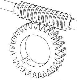
- Advantages: High torque conversion, compact design.
- Disadvantages: Low efficiency due to sliding friction, limited to low-speed applications.
- Applications: Lifts, conveyors, and machinery needing high reduction ratios.
2. Hypoid Gear
Hypoid gears are similar to spiral bevel gears but have an offset axis, allowing for smoother operation and higher contact ratios.
- Advantages: Reduced noise, improved load distribution.
- Disadvantages: Complex manufacturing, potential for higher costs.
- Applications: Automotive differential systems, industrial drives.
3. Crossed Helical Gear
Crossed helical gears have their axes crossed at an angle, allowing for power transmission between non-parallel shafts.
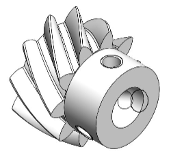
- Advantages: Versatile in application, smooth operation.
- Disadvantages: Limited to lower power applications due to point contact.
- Applications: Light machinery, automatic machines, and small drives.
Related Articles:
 Chamfer vs Bevel vs Fillet: Differences In Purpose, Angle, Size, Shape, Machining Tools, Cost, Uses
 Different Types of Gears and Their Applications | What is Gear & Understanding Common Gears | CNCLATHING
 ASME Flange Bolt Torque Chart (Calculation Formula & Sequence Pattern)
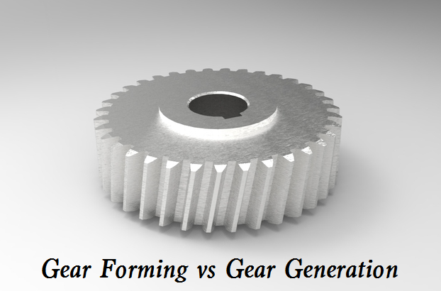 Difference Between Gear Forming and Gear Generating – Gear Forming & Generation Pros and Cons
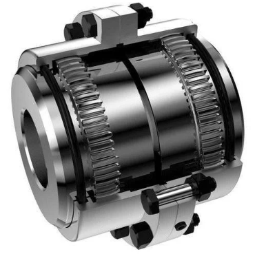 What Is Gear Coupling & How Does It Work – Full & Half Gear Coupling Size Chart
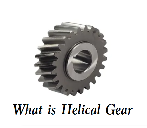 What is Helical Gear – Different Types of Helical Gear and How Do They Work