- Home
- Machining techniques
- CNC Machining Services
- Cooperative supply services
- Designs
- Materials
- Finishing Services
- Shop
- Products
- Guide
- About Us
- Contact Us
2023.5.18
When using a centerless grinding machine for machining, the workpiece is not mechanically constrained, how does a centerless grinding machine work? Today we’ll get into the advantages, working principle and basic parts of a centerless grinder.
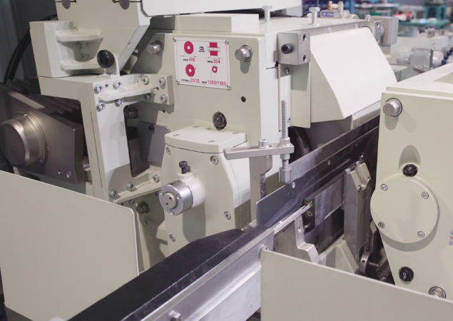
A centerless grinding machine is a machine tool that uses CNC technology to grind the surface of a workpiece using grinding tools. Most grinders use high-speed rotating grinding wheels for grinding, while a few use other grinding tools such as oilstones, abrasive belts, and free abrasives for processing, such as honing machines, ultra-precision machining machines, abrasive belt grinders, grinders, and polishing machines. Capable of processing materials with higher hardness, such as hardened steel, hard alloys, etc; It can also process brittle materials, such as glass and granite. Grinding machines can perform high-precision and low-surface roughness grinding, as well as high-efficiency grinding, such as strong grinding. There are also CNC surface grinding machines, CNC centerless grinding machines, CNC inner and outer cylindrical grinding machines, CNC coordinate grinding machines, CNC forming grinding machines, and so on.
The machining accuracy and efficiency of centerless grinding machines are among the highest among all grinding equipment, suitable for processing complex and irregular parts. This device can achieve computer control, eliminate human errors, and improve the accuracy of equipment processing. Operators can also achieve compensation and optimization control of equipment accuracy through computer software, better-controlling equipment production. Operators can convert the tool change function based on their own judgment, reduce clamping times, and improve machining accuracy.
The grinding wheel rotates at high speed for grinding, while the guide wheel rotates in the same direction at a slower speed, thereby driving the workpiece to rotate and perform circumferential feed. During penetration grinding, axial feed is achieved by adjusting the inclination angle of the guide wheel axis, and during penetration grinding, radial feed is achieved by moving the guide wheel frame or grinding wheel frame. When centerless grinding, the center of the workpiece must be higher than the center line between the grinding wheel and guide wheel, which makes it impossible for the contact points between the workpiece and the grinding wheel and guide wheel to be symmetrical. Therefore, some raised surfaces on the workpiece can gradually be rounded during multiple rotations. If the top surface of the supporting plate is horizontal and the center of the workpiece is adjusted to be at the same height as the center of the grinding wheel and guide wheel, when there is a raised point on the workpiece that contacts the guide wheel, the opposite side of the raised point is ground into a concave pit, and its depth cannot be reduced to the height of the raised point. After the workpiece rotates 180 degrees, the raised points come into contact with the grinding wheel. At this point, the concave hole is exactly at the angle of the guide wheel, and the raised points cannot be ground flat. At this point, the outer surface of the workpiece is an equal-diameter edge circle. So, the key to rounding the workpiece is that the center of the workpiece is higher than the centerline between the grinding wheel and the guide wheel, but the higher distance should not be too large, otherwise, the vertical component of the guide wheel on the workpiece may cause the workpiece to jump and affect the surface quality of the machining. Generally, h=(0.15-0.25) d, where d is the diameter of the workpiece. A centerless cylindrical grinder does not have a headstock or tailstock but is supported by a support plate and a guide wheel, and is ground with a grinding wheel. The upper surface of the support plate is tilted by 30 ° to 50 ° so that the workpiece is tightly pressed against the guide wheel by cutting force. The axis of the guide wheel has a tilt angle relative to the axis of the grinding wheel α (1~5°). The guide wheel rotates at a low speed and relies on friction to drive the workpiece to rotate. Due to the existence of an inclination angle, the velocity direction at the contact point between the guide wheel and the workpiece is oblique, which can be divided into two velocity components: one is to rotate the workpiece, and the other is to generate axial feed motion of the workpiece.
– Machine bed: The machine base is a sturdy, heavy-duty cast iron structure that supports other parts of the machine. It accommodates the hydraulic oil tank and grinding wheel head components. A machine equipped with a sturdy base will increase the rigidity of the machine and reduce vibration.
– Swivel plate: A rotary plate is a rectangular cast iron component installed on the base with a trunnion. By adjusting the turntable, the adjustment wheel can be correctly aligned with the grinding wheel.
– Grinding wheel: A grinding wheel is a cutting tool used to remove parts of a workpiece. It is made of abrasive particles and binders.
– Grinding wheel dresser: The grinding wheel dresser is installed behind the grinding wheel and uses diamonds to trim the grinding wheel.
– Grinding wheel head: The grinding head that fixes the grinding wheel is a movable shell that is bolted to the base.
– Wheel head and spindle: There is a spindle in the grinding wheel head that supports the grinding wheel. A high-precision spindle supports and rotates the grinding wheel.
– Lower slide: A lower slide is installed on a rotating plate to control the adjustment wheel and workpiece holder while advancing or retracting towards the grinding wheel.
– Upper slide: installed on the lower slide to control the adjustment wheel towards or away from the workpiece frame. It includes a driving device for adjusting the wheels.
– Dual compensation infeed assembly: The dual compensation infeed assembly consists of two precision ball threaded rods and is installed on the upper and lower slide rails. This component is used to adjust the machine to fit the size of the workpiece.
– Regulating wheel: The regulating wheel is made of rubber binder mixed with abrasive. It has the function of supporting the workpiece and driving it to rotate.
– Regulating wheel dresser: The adjusting wheel dresser is installed on the outer shell of the adjusting wheel and is trimmed with diamonds.
– Regulating wheel head: The adjusting wheel head is installed on the surface of the upper slide rail and can rotate on that surface. The spindle includes the adjustment wheel and the adjustment wheel.
– Work rest: The work rest is installed on the lower slider to support the blade.
– Blade: The blade is fixed on the workpiece holder to support the workpiece.
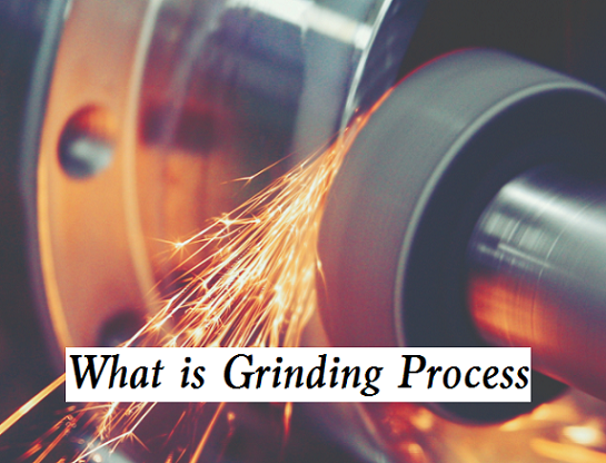 What is Grinding Process & How It Works – Different Types of Grinding
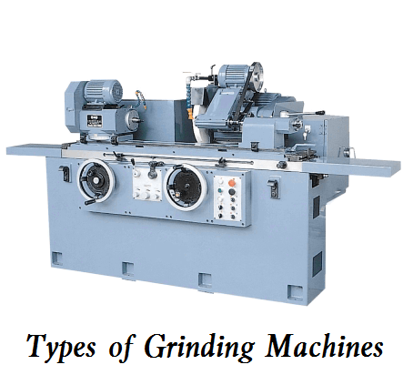 Different Types of Grinding Machines and How to Use a Grinder – How Does a CNC Grinder Work
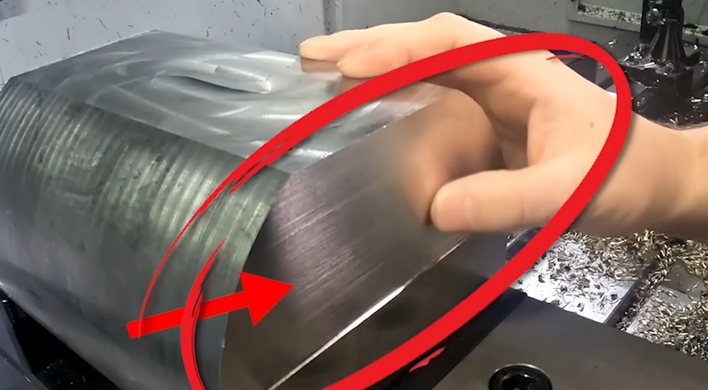 How To Reduce & Stop Chatter Vibration in CNC Milling/Turning/Drilling/Grinding Lathe?
 How to Convert Precision Milling Machine Into CNC Milling | CNCLATHING
 7 Different Types Of CNC Machines – CNC Lathe, CNC Milling Machine & More | CNCLATHING
 Top 12 CNC Machining & Programming Experiences | CNCLATHING
