The following are two basic operation methods:
Turning on and returning to zero is an operation often used by processors. In popular words, it is to return the coordinates of the machine tool to the initial position, and then use this coordinate point as the reference point to realize subsequent processing operations and task control. At the same time, it can also provide reference points to facilitate the adjustment and setting of tool compensation and gap compensation in the second half of machining. According to the implementation method and detection device, there are mainly two methods of zero return: grid method and magnetic switch.
As the two main ways of returning to zero in machining centers, their effects and execution methods are completely different. Among them, for the magnetic switch zeroing, this method has poor zeroing accuracy and effect due to the defect of its own positioning drift phenomenon. Therefore, this method is only applied to early machining centers, and now high-precision machining centers are basically not used, so this method can be ignored.
The principle of grid zeroing is to realize the effective zeroing of machine tools through two parts: grating ruler and pulse encoder. This zeroing method has high precision and good flexibility. It is the mainstream zeroing method of CNC machine tools at present; This method is divided into absolute grid method and incremental grid method.
The absolute grid method means that after the machine tool completes the zero return operation during the first commissioning, this detail can be permanently stored in the zero position, and then this step of operation is not needed.
The incremental grid method needs to complete the coordinate axis setting manually. In addition, it also needs to control the signal of the machine tool control device through pulses, so as to query the switch position of the zero point, so as to complete the process of returning to zero. See the following for operation:
The machine tool must be reset when it is started, and the action process generally has four forms:
1. In the manual mode, the coordinate axis approaches the zero point at high speed (V1), and the zero return operation is started when it approaches the zero point. The system controls the coordinate axis to continue to move to the zero point at low speed (V2). After triggering the zero switch, the system starts to query the zero mark pulse sent by the detection element. After receiving the zero mark pulse, the system sends a grid pulse control signal to control the braking of the zero return axis, and the displacement counter is cleared at the same time, At this time, the position of the zero return axis is the zero point of the coordinate system of the NC machine tool, and the zero return ends;
2. The coordinate axis first approaches the zero point at high speed (V1). After triggering the zero point switch, the system controls the coordinate axis to continue to move to the zero point at low speed (V2). After crossing the zero point switch, the system starts to query the zero mark pulse, and the subsequent actions are the same as operation 1;
3. The coordinate axis first approaches the zero point at high speed (V1). After triggering the zero switch, the system controls the coordinate axis braking, and then moves in the opposite direction at speed (V2). The system starts to query the zero mark pulse, and the subsequent actions are the same as operation 1;
4. The coordinate axis first approaches the zero point at high speed (V1). After triggering the zero point switch, the coordinate axis braking stops, and then moves across the zero point switch in reverse at micro speed (V3), and then moves to the zero point at speed (V2). When the zero point switch is triggered again, the system starts to query the zero mark pulse, and the subsequent actions are the same as operation 1.
 CNC Mill Zero Setting Tutorial – How to Set Zero Point for a CNC Milling Part? | CNCLATHING
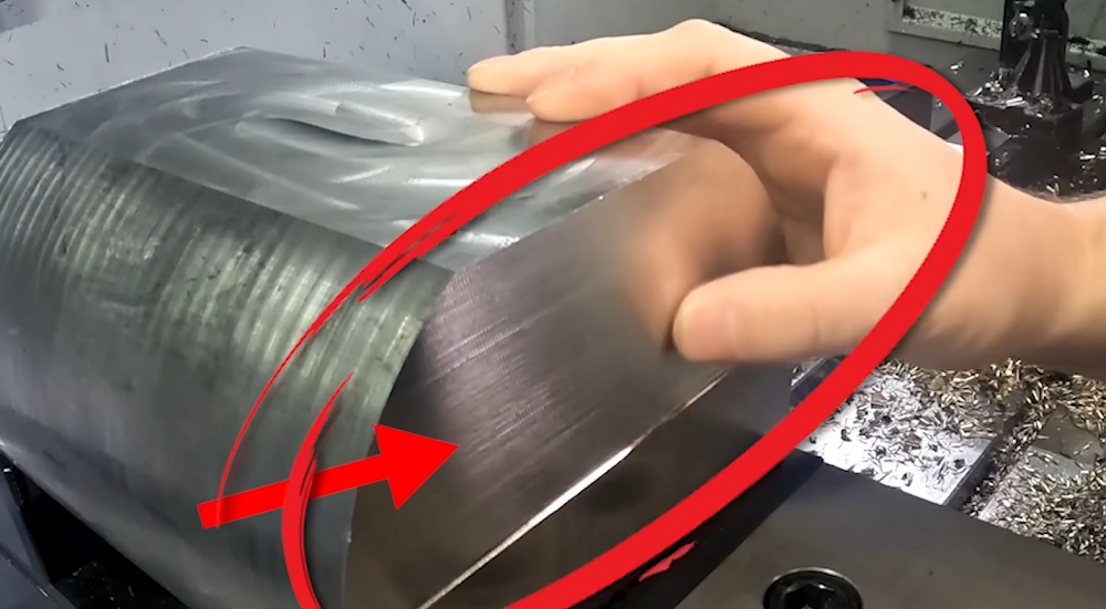 How To Reduce & Stop Chatter Vibration in CNC Milling/Turning/Drilling/Grinding Lathe?
 CNC Machine Installation Tips – How To Assemble & Install CNC Machine Tools The Right Way
 Polyamide Vs. Nylon Vs. Polyester: Properties, Uses, Advantages & Disadvantages
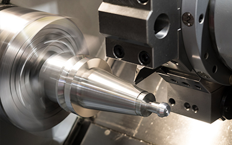
 What is Grooving Operation in Lathe Machine: Lathe Grooving Tool & Dimensions
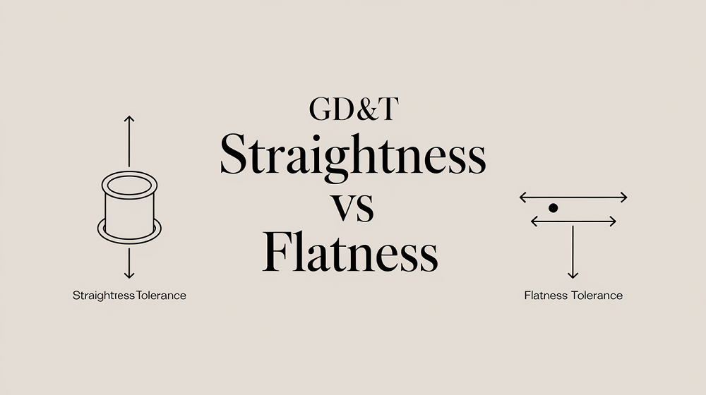 Straightness vs Flatness – Difference Between Flatness and Straightness
