
A keyway ensures that only keys of specific shapes can be inserted and operated on the lock to prevent incorrect key insertion into the lock cylinder. How to design the accurate keyway? This guide provides a comprehensive overview of keyways, how they function, and the dimensions involved in their design.
What Are Keys and Keyways in Engineering, and How Do They Work?
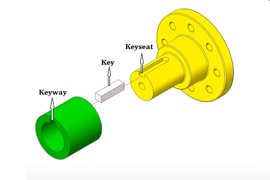
In mechanical engineering, a key is a crucial machine element that connects a rotating component to a shaft, preventing relative rotation and facilitating torque transmission. This system relies on a keyway and keyseat – slots and pockets where the key fits – forming a keyed joint that can permit axial movement between parts. Gears, couplings, washers, and pulleys are all common keyed components.
A keyway is a slot or groove machined into a shaft or hub to accommodate a key. The key and keyway work together to form a keyed joint. The primary purpose of this joint is to connect rotating components to the shaft. As the following image shows, keyways are slots created on the internal parts (bores), and keyseats refer to the slots on the external parts (shafts). This connection prevents relative rotation between the shaft and the component, ensuring they rotate together and allowing for efficient torque transmission. Common types of keyways include rectangular, square, and half-round keyways. The choice of keyway type depends on the application and the type of key being used. Keyway shafts are widely used in mechanical systems where precise and secure connections are essential.
When designing keyways and keys, it is important to consider factors such as the type of load, the material of the shaft and hub, and the required precision of the fit. Improperly fitted keys and keyways can lead to mechanical failures. Standard key sizes are available for various shaft diameters. These sizes are standardized to ensure proper fit and function in different applications.
The keyway of a lock refers to the shape of the hole in the lock cylinder where the key is inserted, which is a channel inside the lock that matches the shape of the key. If you need standard or custom lock components, CNCLATHING offers a diverse selection of high-security door locks and lock parts in the lock cylinder shop, available in different keyways, materials, surface finishes, and dimensions. With competitive prices and a focus on quality, CNCLATHING is your go-to source for a reliable lock cylinder machining supplier.
How to Determine the Sizes of Keyways and Keys?
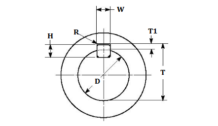
The dimensions of keyways are specified by their width and depth. Key size refers to the dimensions of the key used in a keyed joint and are specified by their width and height.
- Hub Width (W): This is the width of the keyway that is machined into the hub. It is the dimension that corresponds to the width of the key. If the keyway hub width is specified as 8 mm, the key must also be 8 mm wide to fit correctly.
- Hub Depth (T1): This is the depth of the keyway in the hub. It determines how far the key will extend into the hub.
- Radius (R): This refers to the radius at the bottom of the keyway in the hub. It is the curvature at the base of the keyway.
- Key Width (W): This is the width of the key, typically measured across its broadest part (e.g., the part of the key that interacts with the lock’s internal components), same as the keyway width.
- Height (H): This is the height of the key, typically measured from the bottom edge of the key to the top of the blade.
What are the uses of the keyway radius?
- A radius at the bottom of a keyway reduces stress concentrations that can cause premature failure under cyclic loading.
- The rounded bottom of a keyway simplifies machining, reducing tool wear and enhancing accuracy.
- The radius ensures the key fits properly in the keyway, preventing excessive tightness and facilitating smooth assembly.
- By minimizing stress concentrations, the radius enhances the component’s fatigue resistance, especially under repeated loading.
- A radius improves the keyway’s appearance and aids in guiding the key during assembly for greater reliability.
- Many design standards specify keyway radii to ensure compatibility and proper functioning of components from different manufacturers.
Keyway Design Considerations
- Material Selection: Keys are usually made from steel or other durable materials to withstand the stresses of torque transmission. The choice of material affects the key’s strength and durability.
- Keyway Dimensions: The dimensions of the keyway must be carefully calculated to ensure a proper fit. This includes the width, depth, and length of the keyway, which should accommodate the specific type of key being used.
- Load Conditions: The design must account for the type of loads the keyed joint will experience, including static, dynamic, and shock loads. Keyed joints are generally not suitable for alternating directional loads.
- Installation and Maintenance: Ease of installation and the ability to disassemble the joint for maintenance are important considerations. Some keys, like Gib-head keys, are designed for easy removal.
Key and Keyway Dimensions Chart in MM (Metric)
The key dimensions listed in the following table refer to nominal size, which provides a standardized reference for selecting and specifying keys to ensure compatibility between components from different manufacturers. Engineers use nominal key dimensions during the design phase to specify the required information, and then we can produce keys to these sizes. Nominal, Min, and Max data provide the nominal, minimum, and maximum dimensions for the keyway and key. They are critical for ensuring proper fit and function within manufacturing tolerances.
|
Shaft |
Key |
Keyway |
||||||||
|---|---|---|---|---|---|---|---|---|---|---|
|
Diameter (D) |
Nominal Size |
Hub Width(W) |
Hub Depth (T1) |
Radius (R) |
||||||
|
Over |
Thru |
Width (W) |
Height (H) |
Nominal |
Min |
Max |
Min |
Max |
Min |
Max |
|
6 |
8 |
2 |
2 |
2 |
-.0125 |
+.0125 |
1.0 |
1.1 |
0.08 |
0.16 |
|
8 |
10 |
3 |
3 |
3 |
-.0125 |
+.0125 |
1.4 |
1.5 |
0.08 |
0.16 |
|
10 |
12 |
4 |
4 |
4 |
-.0150 |
+.0150 |
1.8 |
1.9 |
0.08 |
0.16 |
|
12 |
17 |
5 |
5 |
5 |
-.0150 |
+.0150 |
2.3 |
2.4 |
0.16 |
0.25 |
|
17 |
22 |
6 |
6 |
6 |
-.0150 |
+.0150 |
2.8 |
2.9 |
0.16 |
0.25 |
|
22 |
30 |
8 |
7 |
8 |
-.0180 |
+0180 |
3.3 |
3.5 |
0.16 |
0.25 |
|
30 |
38 |
10 |
8 |
10 |
-.0180 |
+0180 |
3.3 |
3.5 |
0.25 |
0.40 |
|
38 |
44 |
12 |
8 |
12 |
.-0215 |
+.0215 |
3.3 |
3.5 |
0.25 |
0.40 |
|
44 |
50 |
14 |
9 |
14 |
.-0215 |
+.0215 |
3.8 |
4.0 |
0.25 |
0.40 |
|
50 |
58 |
16 |
10 |
16 |
.-0215 |
+.0215 |
4.3 |
4.5 |
0.25 |
0.40 |
|
58 |
65 |
18 |
11 |
18 |
.-0215 |
+.0215 |
4.4 |
4.6 |
0.25 |
0.40 |
|
65 |
75 |
20 |
12 |
20 |
-.0260 |
+.0260 |
4.9 |
5.1 |
0.40 |
0.60 |
|
75 |
85 |
22 |
14 |
22 |
-.0260 |
+.0260 |
5.4 |
5.6 |
0.40 |
0.60 |
|
85 |
95 |
25 |
14 |
25 |
-.0260 |
+.0260 |
5.4 |
5.6 |
0.40 |
0.60 |
|
95 |
110 |
28 |
16 |
28 |
-.0260 |
+.0260 |
6.4 |
6.6 |
0.40 |
0.60 |
|
110 |
130 |
32 |
18 |
32 |
-.0310 |
+.0310 |
7.4 |
7.6 |
0.40 |
0.60 |
|
130 |
150 |
36 |
20 |
36 |
-.0310 |
+.0310 |
8.4 |
8.7 |
0.70 |
1.00 |
|
150 |
170 |
40 |
22 |
40 |
-.0310 |
+.0310 |
9.4 |
9.7 |
0.70 |
1.00 |
|
170 |
200 |
45 |
25 |
45 |
-.0310 |
+.0310 |
10.4 |
10.7 |
0.70 |
1.00 |
|
200 |
230 |
50 |
28 |
50 |
-.0310 |
+.0310 |
11.4 |
11.7 |
0.70 |
1.00 |
|
230 |
260 |
56 |
32 |
56 |
-.0370 |
+.0370 |
12.4 |
12.7 |
1.20 |
1.60 |
|
260 |
290 |
63 |
32 |
63 |
-.0370 |
+.0370 |
12.4 |
12.7 |
1.20 |
1.60 |
|
290 |
330 |
70 |
36 |
70 |
-.0370 |
+.0370 |
14.4 |
14.7 |
1.20 |
1.60 |
|
330 |
380 |
80 |
40 |
80 |
-.0370 |
+.0370 |
15.4 |
15.7 |
2.00 |
2.50 |
|
380 |
440 |
90 |
45 |
90 |
-.0435 |
+.0435 |
17.4 |
17.7 |
2.00 |
2.50 |
|
440 |
500 |
100 |
50 |
100 |
-.0435 |
+.0435 |
19.5 |
19.8 |
2.00 |
2.50 |
Related Articles:
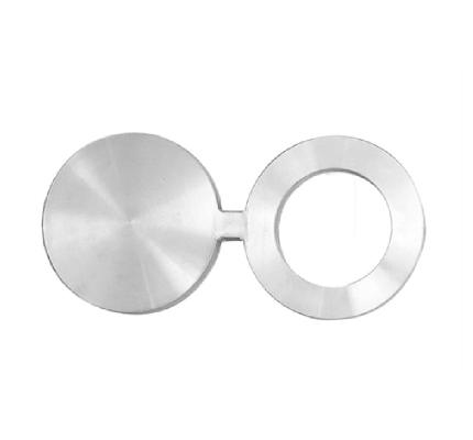 What Is a Blind Flange – Blind Flange Dimensions Chart in MM & Inch (Class 150 to 2500)
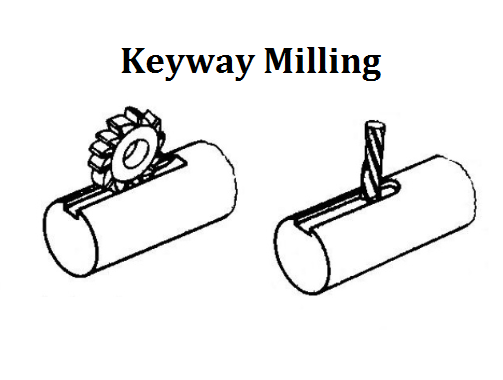 How to Cut a Keyway on a Milling Machine | Guide to Keyway Milling Operation & Cutters| CNCLATHING
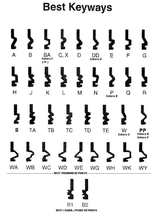 What is A Keyway – Lock Keyway Types, Designs & Schlage vs Kwikset | CNCLATHING
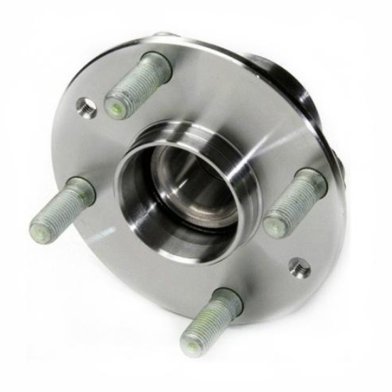 Guide to Automobile Hub: Materials, Manufacturing Technology and Difference
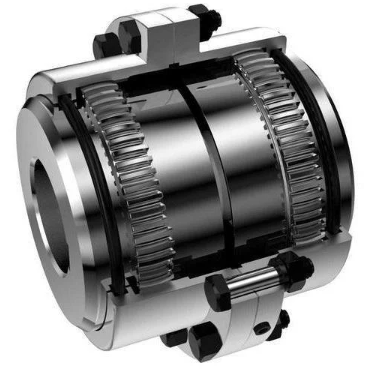 What Is Gear Coupling & How Does It Work – Full & Half Gear Coupling Size Chart
 Stainless Steel Families & Grades Chart (Chemical Composition, Properties & Uses)