
A reamer is a cutting tool used to adjust pre-drilled holes to a specified size or to finish them with high precision. Reamers are widely used in the machining of metals, plastics, and other materials, finding applications in industries such as aerospace, shipbuilding, and mechanical manufacturing. The standard diameter sizes and tolerance specifications of reamers are crucial parameters, affecting both the size of the reamed hole and the workpiece’s precision and surface roughness. When selecting a reamer, it is important to consider processing requirements, hole size, precision requirements, and the type of reamer head to ensure quality and efficiency. Here, we discuss the dimensions and tolerances related to reaming in CNC machining.
What is the Reamer Size?
The diameter of the reamer is one of the key factors in selecting a reamer. The choice of reamer size should be based on specific processing needs, the material of the workpiece, and the precision of the machine tool. Improper size selection can affect the quality and efficiency of the reaming process.
Reamer Tool Size
- Single-Edge Reamer Specifications
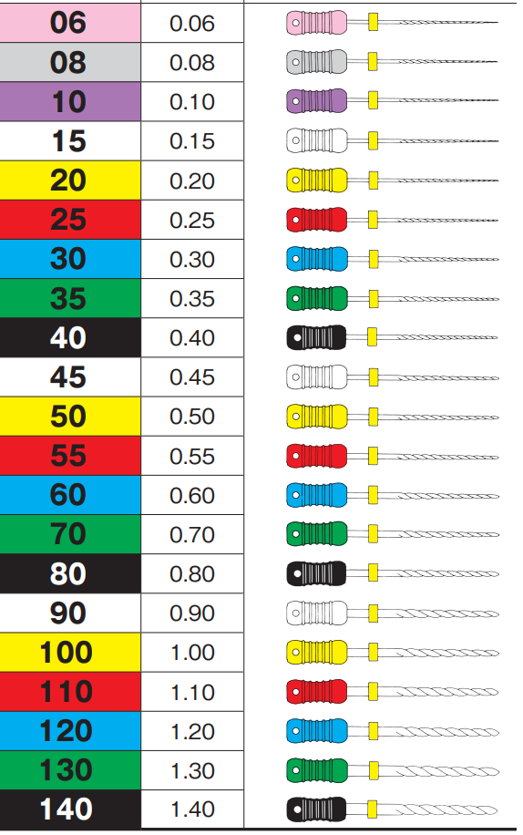
Reamer Head Diameter: Generally ranges from 3mm to 20mm, with 8mm, 10mm, and 12mm being the most common.
Length: Ranges from 50mm to 150mm, chosen according to the depth of the hole or the thickness of the workpiece.
Angle: Generally 90 degrees, with some reamers at 60 degrees or 45 degrees.
- Double-Edge Reamer Specifications
Reamer Head Diameter: Generally ranges from 4mm to 25mm, with 10mm, 12mm, and 16mm being the most common.
Length: Ranges from 55mm to 150mm, similar to single-edge reamers, chosen according to the depth of the hole or the thickness of the workpiece.
Angle: Generally 60 degrees or 90 degrees. 60-degree double-edge reamers are more suitable for soft materials (e.g., aluminum alloys, brass), while 90-degree double-edge reamers are suitable for hard materials (e.g., steel, stainless steel).
Additionally, the shape of the reamer head varies, including straight shank, polished, T-shaped, long shank, etc. The shape should be chosen based on the shape of the workpiece, the position of the hole, and the difficulty of the processing.
Reamer Diameter Calculation & Formula
The reamer diameter D can be calculated using the formula: D=2×√[(F+T)÷(π×S)]
where F is the feed per tooth, T is the cutting depth, S is the material’s modulus of elasticity, andπ=3.14.
For example, if F=0.25mm, T=2mm, and S=2×10^5N/mm2, then: D=2×√[(0.25+2)÷(3.14×2×10^5)]=17.4mm
Standard Reamer Size Selection
Selecting the reamer diameter should be based on specific processing needs and application scenarios. Generally, reamer diameters are categorized as follows:
Small Diameter Reamers: Diameter between 2mm and 8mm, mainly used for small and precise holes.
Medium Diameter Reamers: Diameter between 8mm and 20mm, suitable for general hole processing.
Large Diameter Reamers: Diameter between 20mm and 50mm, mainly used for large or special holes, such as those in large machinery parts.
When performing reaming, follow the principles of “first rough, then fine; first shallow, then deep; first slow, then fast; first small, then large” to ensure smooth processing and high efficiency.
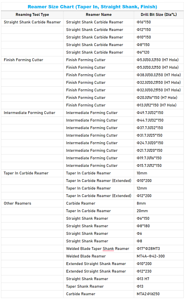
Reamer Drill Bit Size Chart (Taper In, Straight Shank, Finish)
The following table lists the basic drill bit diameters and lengths provided by different reamer tools:
What is the Reamer Drill Size?
A reamer drill size refers to the specific diameter of the reamer tool used to enlarge or finish a pre-drilled hole to an exact size, also known as the reamer drill bit size. Reamers are precision tools that ensure the hole is smooth and accurate in diameter. The size of a reamer is typically stated in either inches (imperial system) or millimeters (metric system), depending on the specification required.
Reamer Drill Size Formula
The formula to calculate the drill size (DS) is: DS=RS−US+OS
where:
Reamer Size (RS): The final size you want to achieve using the reamer.
Drill Size (DS): The size of the drill bit you need to use before reaming.
Undersize (US): The amount by which the drill size is smaller than the reamer size.
Oversize (OS): The extra material allowance for reaming.
For example, if RS = 12mm, US = 0.2mm, and OS = 0.05mm: DS=12mm−0.2mm+0.05mm=11.85mm
Reamer Drill Size Chart
To help you understand the relationship between reamer sizes, drill bit sizes, and the resulting hole sizes, here’s a simplified version of a reamer size table:
| Reamer Size | Drill Bit Size | Drill Size (Decimal) | Hole Size (Inches) |
|---|---|---|---|
| 1/16″ | 1/16″ | 0.0625 | 0.0625 |
| 5/64″ | 1/16″ | 0.0625 | 0.0781 |
| 3/32″ | 5/64″ | 0.0781 | 0.0938 |
| 7/64″ | 3/32″ | 0.0938 | 0.1094 |
| 1/8″ | 7/64″ | 0.1094 | 0.1250 |
| 9/64″ | 1/8″ | 0.1250 | 0.1406 |
| 5/32″ | 9/64″ | 0.1406 | 0.1563 |
| 11/64″ | 5/32″ | 0.1563 | 0.1719 |
| 3/16″ | 11/64″ | 0.1719 | 0.1875 |
| 13/64″ | 3/16″ | 0.1875 | 0.2031 |
| 7/32″ | 13/64″ | 0.2031 | 0.2188 |
| 15/64″ | 7/32″ | 0.2188 | 0.2344 |
| 1/4″ | 15/64″ | 0.2344 | 0.2500 |
| 17/64″ | 1/4″ | 0.2500 | 0.2656 |
| 9/32″ | 17/64″ | 0.2656 | 0.2813 |
| 19/64″ | 9/32″ | 0.2813 | 0.2969 |
| 5/16″ | 19/64″ | 0.2969 | 0.3125 |
| 21/64″ | 5/16″ | 0.3125 | 0.3281 |
| 11/32″ | 21/64″ | 0.3281 | 0.3438 |
| 23/64″ | 11/32″ | 0.3438 | 0.3594 |
| 3/8″ | 23/64″ | 0.3594 | 0.3750 |
| 25/64″ | 3/8″ | 0.3750 | 0.3906 |
| 13/32″ | 25/64″ | 0.3906 | 0.4063 |
| 27/64″ | 13/32″ | 0.4063 | 0.4219 |
| 7/16″ | 27/64″ | 0.4219 | 0.4375 |
| 29/64″ | 7/16″ | 0.4375 | 0.4531 |
| 15/32″ | 29/64″ | 0.4531 | 0.4688 |
| 31/64″ | 15/32″ | 0.4688 | 0.4844 |
| 1/2″ | 31/64″ | 0.4844 | 0.5000 |
| 9/16″ | 17/32″ | 0.5313 | 0.5625 |
| 5/8″ | 19/32″ | 0.5938 | 0.6250 |
| 11/16″ | 21/32″ | 0.6563 | 0.6875 |
| 3/4″ | 23/32″ | 0.7188 | 0.7500 |
| 7/8″ | 27/32″ | 0.8438 | 0.8750 |
| 1″ | 31/32″ | 0.9688 | 1.0000 |
| Reamer Size (mm) | Drill Bit Size (mm) | Drill Size (Decimal) | Hole Size (mm) |
|---|---|---|---|
| 1.0 | 0.9 | 0.0354 | 1.0 |
| 1.5 | 1.4 | 0.0551 | 1.5 |
| 2.0 | 1.9 | 0.0748 | 2.0 |
| 2.5 | 2.4 | 0.0945 | 2.5 |
| 3.0 | 2.8 | 0.1102 | 3.0 |
| 3.5 | 3.3 | 0.1299 | 3.5 |
| 4.0 | 3.8 | 0.1496 | 4.0 |
| 4.5 | 4.3 | 0.1693 | 4.5 |
| 5.0 | 4.8 | 0.1890 | 5.0 |
| 5.5 | 5.3 | 0.2087 | 5.5 |
| 6.0 | 5.8 | 0.2283 | 6.0 |
| 6.5 | 6.3 | 0.2480 | 6.5 |
| 7.0 | 6.8 | 0.2677 | 7.0 |
| 7.5 | 7.3 | 0.2874 | 7.5 |
| 8.0 | 7.8 | 0.3071 | 8.0 |
| 8.5 | 8.3 | 0.3268 | 8.5 |
| 9.0 | 8.8 | 0.3465 | 9.0 |
| 9.5 | 9.3 | 0.3661 | 9.5 |
| 10.0 | 9.8 | 0.3858 | 10.0 |
| 11.0 | 10.8 | 0.4252 | 11.0 |
| 12.0 | 11.8 | 0.4646 | 12.0 |
| 13.0 | 12.8 | 0.5039 | 13.0 |
| 14.0 | 13.8 | 0.5433 | 14.0 |
| 15.0 | 14.8 | 0.5827 | 15.0 |
| 16.0 | 15.8 | 0.6220 | 16.0 |
| 17.0 | 16.8 | 0.6614 | 17.0 |
| 18.0 | 17.8 | 0.7008 | 18.0 |
| 19.0 | 18.8 | 0.7402 | 19.0 |
| 20.0 | 19.8 | 0.7795 | 20.0 |
| 25.0 | 24.8 | 0.9764 | 25.0 |
What is Reamer Tolerance?
In mechanical manufacturing, determining the reamer diameter tolerance based on the size precision of the hole to be processed is common. The tolerance of the reamer diameter directly affects the size precision of the processed hole, the manufacturing cost of the reamer, and its service life. Dimensional tolerance refers to the maximum allowable deviation from the nominal dimension. In machining, achieving the exact specified dimension is almost impossible, so allowable maximum and minimum dimensions for each part are specified, and the actual dimensions must fall within this range. When selecting a reamer, check the blade diameter tolerance and choose a product suitable for use conditions.
Most mechanical parts use holes and shafts in conjunction. Even if a hole is within the tolerance range, if the hole deviates negatively and the shaft deviates positively, the shaft will not fit into the hole. Therefore, dimensional tolerances are usually determined during the design of the parts, so always check them carefully. Most reamers are made with positive tolerances.
Reamer accuracy grades are typically indicated by letters and numbers, where letters represent tolerance grades, and numbers represent tolerance values. Common tolerance grades include D, H, G, etc., with tolerance values indicated by numbers, such as H7, H8.
Reamer Tolerance Calculation & Formula
Based on practical experience, we summarize the method for determining reamer diameter tolerance as follows:
Assume the upper and lower deviations of the hole in the processed part are ES and EI, respectively, and the upper and lower deviations of the reamer diameter are es and ei, respectively.
es= 2/3 (ES-EI)+EI
ei=es- 1/4(ES-EI)
For example, for a Ø10H9 (0+0.036) hole, the upper deviation of the reamer according to the above formula should be:es= 2 (0.036-0)+0=0.024
The lower deviation of the reamer according to the above formula should be:ei=0.024- 1 (0.036-0)=0.015
Thus, the reamer size and tolerance band for a Ø10H9 (0+0.036) hole should be Ø10+0.015+0.024. According to reference materials, the tolerance for a Ø10H9 reamer is Ø10+0.013+0.023, which is very close to the calculated tolerance, meeting usage requirements.
This method can provide a reference for designing or grinding reamers based on the size precision of the processed hole. However, factors such as machine spindle radial runout, reamer installation deviation, radial runout of each reamer tooth, coolant, and cutting amount can affect the diameter of the reamed hole, often causing it to expand or shrink. Therefore, to meet process requirements, trial reaming is generally necessary. Based on trial reaming results, correct the calculated tolerance band, then grind the reamer for use.
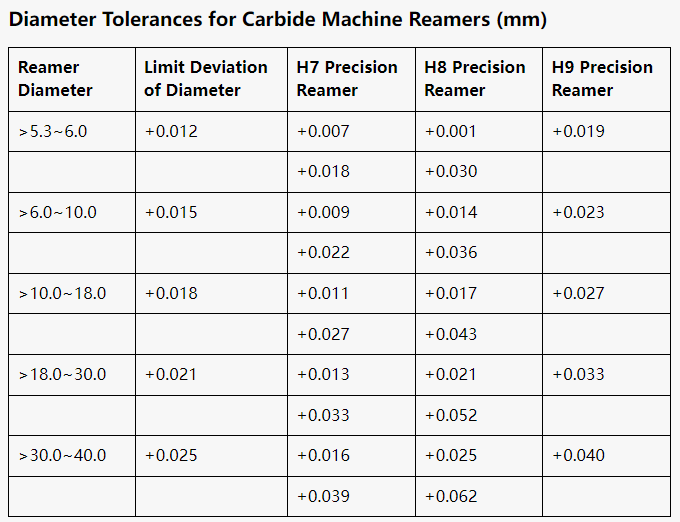
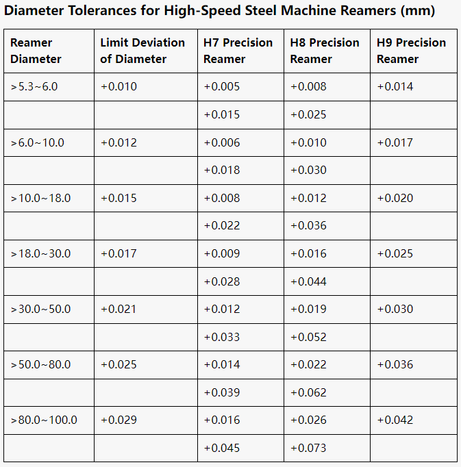
Reamer Tolerance Chart
Depending on the processing requirements and the hole accuracy requirements, it is very important to choose the right accuracy level. Here is a standard reaming tolerance table for different reamer sizes:
Related Articles:
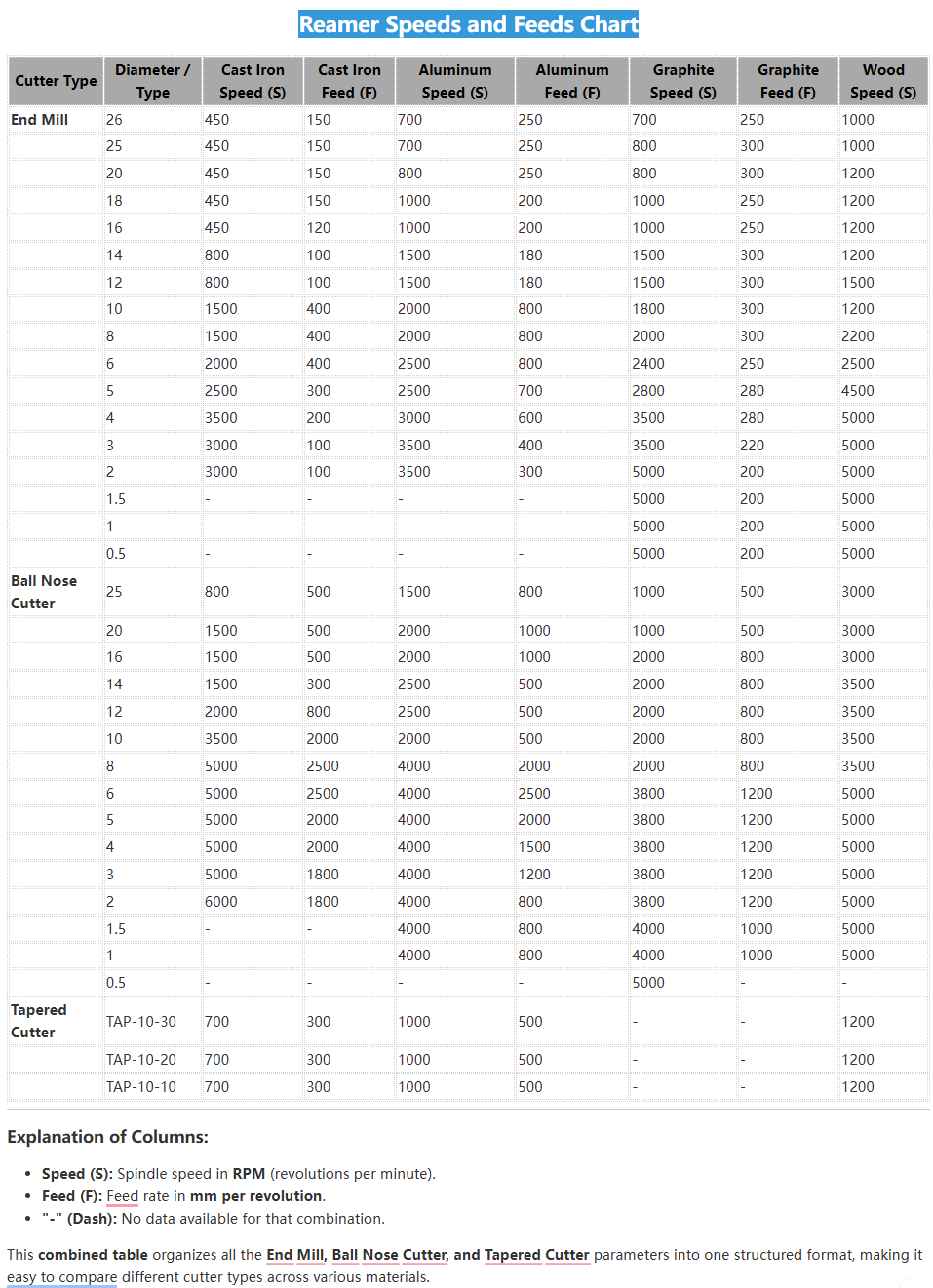 Carbide & HSS Reamer Speeds and Feeds (RPM) Chart in Metric
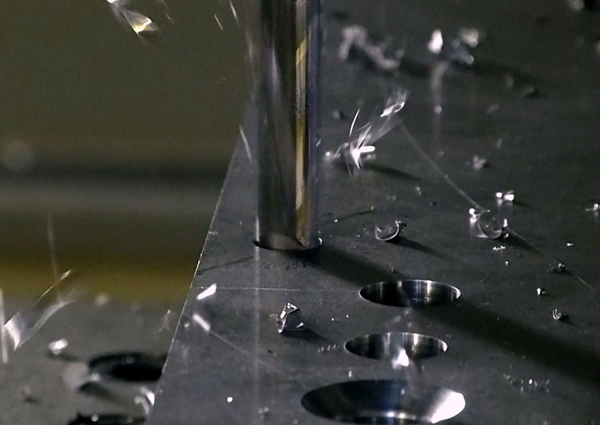 CNC Drilling – The Perfect Collaboration Among Using Drilling, Boring, & Reaming
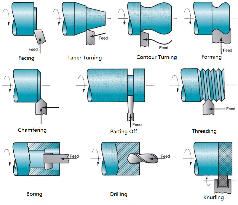 Different Operations on Lathe Machine – What is A CNC Lathe Used for | CNCLATHING
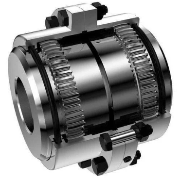 What Is Gear Coupling & How Does It Work – Full & Half Gear Coupling Size Chart
 Drill Bit Selection Guide – How to Select a Right Drill | CNCLATHING
 Best Drill Bit Sharpener 2025 – Top 10 Industrial Drill Bit Sharpening Machines