
Rotary table milling machines, while not as common as standard milling machines, still have unique benefits and specific applications in modern manufacturing. Here we’ll introduce the rotary table milling machine with its definition, parts, diagram, and how to use it.
What Is a Rotary Table Milling Machine?
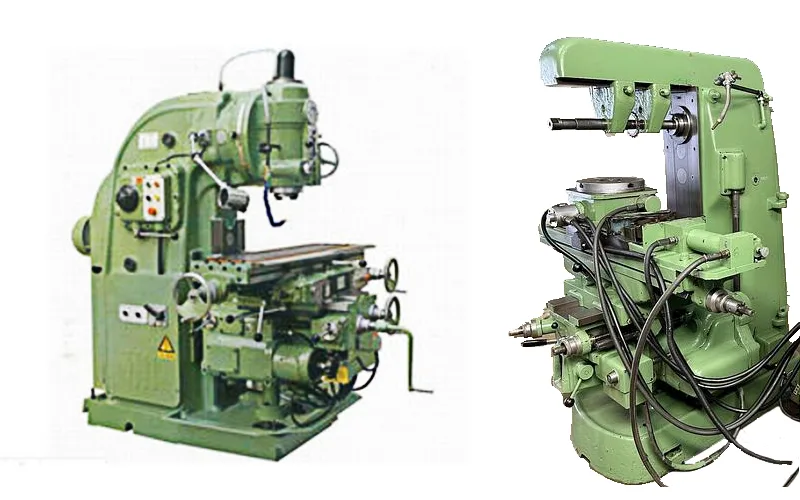
The rotary table milling machine is a type of machine tool that incorporates a rotating table, which is the most distinctive and identifiable feature of the equipment, and typically multiple cutters. One cutter roughs the workpiece, and the others are used for finishing. A rotary table is a mill attachment that converts linear motion into rotary motion. The circular table can rotate 360 degrees around a vertical axis, to machine parts at various angles and heights. The rotary table often has an indexing feature that allows it to be locked into specific angular positions for precision repetitive machining. It usually has a dial or scale to turn the table and keep track of position, with degree markings on the edge. The spindle is typically oriented vertically but can be positioned horizontally for certain operations, a wide range of milling cutters can used on a rotary table mill.
One of the key advantages of a rotary table milling machine is its ability to perform continuous operations. The rotating table allows operators to load and unload workpieces while the machine is in operation, significantly enhancing productivity. In addition, conventional cutting is recommended over climb milling when using a rotary table to avoid potential issues with backlash.
What is the rotary mill used for?
1) Circular Features:
– Bores: Precise circular holes of various diameters.
– Corner rounds: Rounding off sharp corners on workpieces.
– Large rounds: Creating large circular shapes or profiles.
– Partial rounds: Forming arc segments or partial circular features.
2) Angle Work:
– Cutting precise angles on workpieces.
– Creating angled surfaces or bevels.
3) Bolt Patterns:
– Producing evenly spaced holes in a circular pattern.
– Ideal for flanges, gear blanks, or any component requiring symmetrically arranged holes.
4) Spoked Arrays:
– Manufacturing wheel-like structures with evenly distributed spokes.
– Creating radial patterns or features.
5) Edge Radiuses:
– Forming smooth, rounded edges on parts.
6) Tangent Rounds:
– Creating complex curves that transition smoothly from one radius to another.
– Useful in producing contoured surfaces or blended radii.
7) Gear Cutting:
– Rotary tables are often used in gear-cutting operations.
8) Engraving:
– Creating circular text or patterns on flat surfaces.
9) Complex Shapes:
– By combining the rotary motion with linear movements of the mill, complex curved shapes and profiles can be machined.
10) Indexing:
– Precise rotational positioning for repetitive operations.
– Some models offer accuracy down to 10-second increments, allowing for extremely fine adjustments.
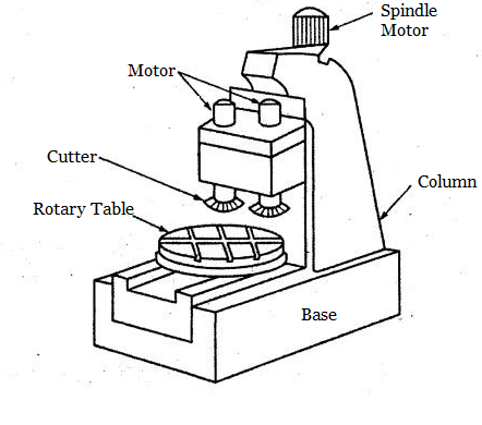
Rotary Table Milling Machine Diagram and Main Parts
The main components of rotary mills typically have these parts, and some of the components can be included or not depending on the product manufacturer or applications.
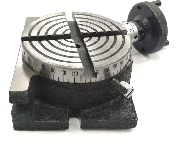
– Table: The circular top surface where the workpiece is mounted. It’s usually graduated in degrees (360°) for precise angular positioning.
– Base: The bottom part that can be mounted to the milling machine bed.
– Column: A vertical component that rises from the base and supports the head and spindle assembly.
– Spindle Motor: The motor that drives the spindle, providing the necessary rotational force for milling.
– Worm gear mechanism: This allows for precise rotation of the table. The product mentions a worm gear ratio of 1:36, meaning one full rotation of the handwheel turns the table by 10 degrees.
– Handwheel: Used to manually rotate the table. It’s typically graduated in smaller increments for fine adjustments.
– T-slots: Slots on the table surface for securing workpieces or fixtures. The product mentions 4 slots.
– Clamping mechanism: To lock the table in position after rotation.
– Vertical mounting provision: Allows the table to be used in both horizontal and vertical orientations.
– Center hole: This is for mounting additional accessories or for alignment purposes.
– Vernier scale: This is used to read precise angular measurements.
– Zero setting mechanism: Allows the handwheel to be set to zero at any position.
– Stepper motor (for CNC versions): To allow for automated rotation.
– Dividing plates (optional): For precise division of the circle into equal parts.
– Tailstock (optional): To support longer workpieces when the table is used horizontally.
– Chuck (optional): For holding cylindrical workpieces (e.g., the 3-jaw chuck mentioned in one product).
Below is the diagram of a milling machine with a rotary table:
How to Use a Rotary Table on a Milling Machine?
You can use a rotary table milling machine to perform precision curved cuts and positioned cuts on round stock, as well as drill holes accurately. Let’s take the drilling operation as an example, to see how to use a rotary table on a mill.
1. Prepare the workpiece by pre-drilling, threading, and center drilling it on a lathe, then inscribe a circle to mark the boundary for hole placement.
2. Secure the rotary table by bolting it down on one side using clamping blocks. The other side may require a separate mount for stability during cutting operations. Then mount the workpiece using a Morse taper.
3. Position the workpiece so the drill bit aligns with the inscribed circle, marking the perimeter for hole placement.
4. Use a countersink tool to create starting points for each hole, preventing drill bit wandering.
5. Drill the first hole at a very low speed when drilling small or deep holes.
6. Rotate the table at 120 degrees and repeat the countersinking and drilling process for the second hole.
7. Rotate the table another 120 degrees (240 degrees total from the start) and repeat the process for the third hole.
8. Machine off excess material for a smooth finish and verify that the holes go all the way through the workpiece.
9. Compare the drilled piece to an existing part for accuracy, with plans to bore the initially undersized holes by hand to achieve the final desired size.
Related Articles:
 Face Mill vs Shell Mill vs End Mill Cutters: Differences & When To Use Each Milling Cutter?
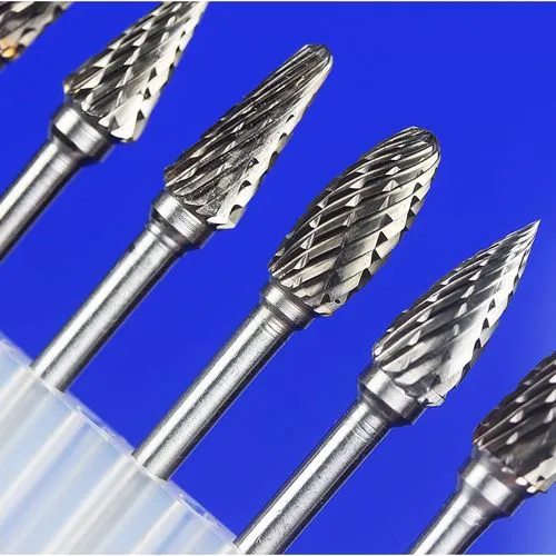 Carbide Rotary Burr Cut Types: Main Cutters, Differences in Cut Sizes & Suitable Materials
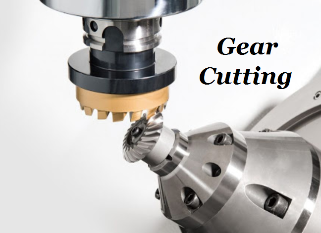 Gear Cutting Process, Materials & Tools | What is Gear Cutting | CNCLATHING
 What is Helical Gear – Different Types of Helical Gear and How Do They Work
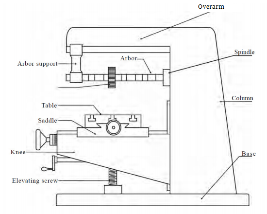 Column And Knee Type Milling Machine: Definition, Types, Parts, Diagram and Construction | CNCLATHING
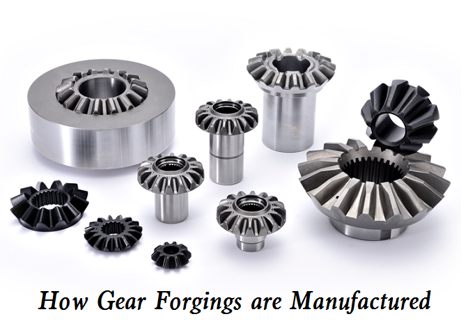 How Gear Forgings are Manufactured | Gear Forging vs Gear Casting