
Two important geometric tolerances in GD&T are straightness and flatness. Both control the form of a surface or feature without relating it to other design elements. However, straightness and flatness apply to different geometric entities – straightness controls the linearity of edges or axes, while flatness controls the evenness of surfaces.
Proper application and interpretation of straightness and flatness tolerances are critical to ensure manufactured parts fit and function as intended. In this blog, we discuss the key differences between these two GD&T controls: what each symbol represents, how they are annotated on technical drawings, common tolerance values, measurement methods, and their distinctive applications to lines, axes, or surfaces. A clear understanding of straightness versus flatness is essential for designers to communicate tolerances accurately, and manufacturers to evaluate and validate feature geometries.
What is Straightness in GD&T?
In Geometric Dimensioning and Tolerancing (GD&T), straightness is a tolerance that specifies that a line or surface must be perfectly straight within a specified tolerance zone. It ensures that the feature does not deviate beyond this zone, allowing for proper alignment and functionality in assembly or mating applications. Straightness is the deviation from a geometrically straight line of a linear element such as an axis or edge. There are no size limitations in straightness, unlike other tolerances.
Straightness Symbol in Drawing
The straightness symbol in geometric dimensioning and tolerancing (GD&T) is a straight line. When using the ASME Y14.5 or ISO 1101 standards, straightness is indicated by annotating a feature on a technical drawing with this symbol within a feature control frame.
The feature control frame for straightness typically consists of the following:
The straightness symbol (a straight line).
The tolerance value specifies the allowable deviation from perfect straightness.
Optionally, additional information may include datum references if the straightness needs to be related to specific datum planes or points.
Here’s how a feature control frame for straightness might look on a technical drawing:
┌───────┐
│ ─ │
│ 0.05 │
└───────┘
In this example, the straight line in the top section of the frame is the symbol for straightness, and “0.05” in the middle section represents the tolerance value in the same units as the drawing (e.g., millimeters or inches). There is no datum reference in this example, indicating that the straightness is to be evaluated independently of other features.
When placed on a drawing, this feature control frame would be connected to the feature that it controls with a leader line or would be placed directly beside the dimension of the feature to which it applies.
Straightness Drawings
To provide an example of how straightness might be indicated on a technical drawing, let’s take the case of a straight shaft. The straightness tolerance would ensure that the axis of the shaft doesn’t deviate from a straight line by more than the specified tolerance.
Here are some examples of how to show the straightness of the technical drawing:
Straightness of a Cylindrical part
For a cylindrical part, straightness is specified on the outer contour. In the figure below, the straightness of the reference axis is indicated to be 0.02 or less. In this case, the tolerance zone is between two parallel planes with an interval of the tolerance value (0.02). Measurement needs to be within this tolerance of 0.02mm.

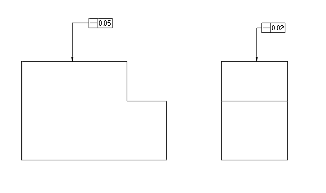
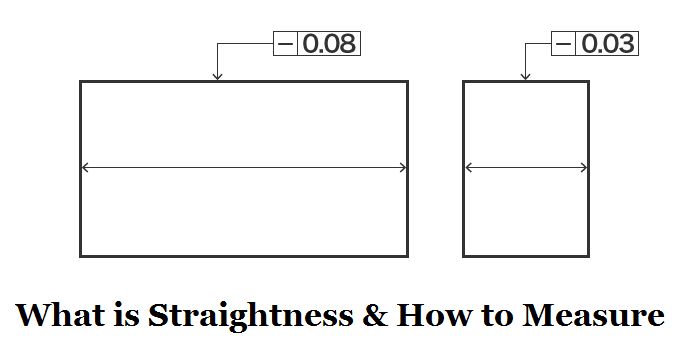
Straightness of the top surface of a plate
For the top surface of a plate, straightness can be specified in both the longitudinal (x) direction and transverse (y) direction. In the figure below, straightness is indicated as 0.05 or less in the long direction and 0.02 or less in the short direction. This allows accurate reflection of design intents that are difficult to express in tolerance design. The tolerance zone is between two parallel straight lines with an interval of the tolerance value t (x direction 0.05, y direction 0.02) that are parallel to the projected surface.
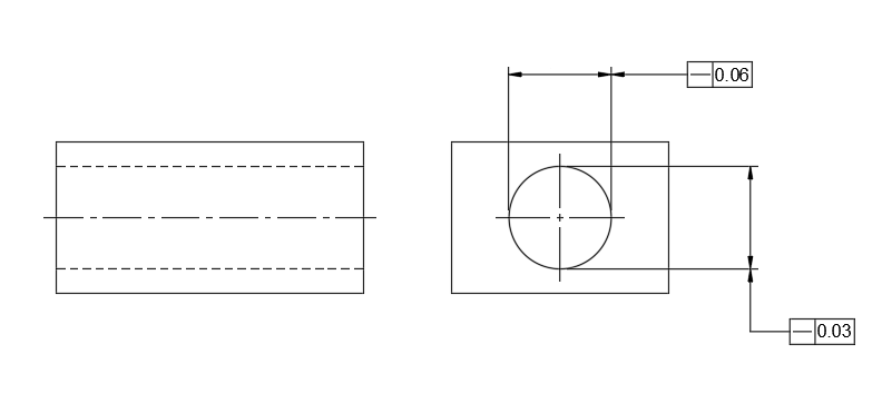
Straightness of a hole axis
Straightness can be specified in two perpendicular directions of the x and y axes for a hole axis. In this figure, the tolerance value is indicated as 0.06 in the X axis direction and 0.03 in the Y axis direction.
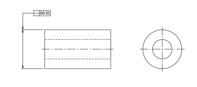
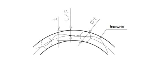
Straightness of a cylindrical part axis with no direction specified
For a cylindrical part, straightness can be specified without defining the direction of the axis. As shown in the figure below, straightness is specified opposite to the dimensional lines indicating the diameter of the axis. However, unlike straightness of a hole axis, there are no restrictions in two perpendicular directions, and it is a cylindrical tolerance zone with no direction specified.
Straightness Tolerance Standard
The straightness tolerance is often specified on a technical drawing, using the standard symbols and notation from the ASME Y14.5 or ISO 1101 geometric dimensioning and tolerancing (GD&T) standards.
Straightness tolerances will vary depending on the size of the feature and the precision required for the particular application. Here is a simplified table that might be found in a general engineering handbook or standards manual, illustrating common straightness tolerances for different ranges of feature sizes.
| Feature Size Range (mm) | Straightness Tolerance (mm) |
| 0 to 10 | 0.02 |
| 10 to 30 | 0.05 |
| 30 to 100 | 0.1 |
| 100 to 300 | 0.2 |
| 300 to 1000 | 0.3 |
| 1000 and up | 0.5 or greater |
Please note that these values are for illustrative purposes only. Actual tolerances would be determined based on the specific requirements of the part, its function, the manufacturing process, and the industry standards applicable to the particular field (e.g., aerospace, automotive, medical devices).
When specifying straightness in a technical drawing, the tolerance would be annotated alongside the feature it applies to, often using a feature control frame under the relevant dimension or as a note.
For precise applications, it is always best to refer to the actual standards and engineering specifications relevant to the project you are working on. The values provided above are general and may not be suitable for all applications.
Straightness Common Zone
The straightness common zone is a concept used in Geometric Dimensioning and Tolerancing (GD&T) to define a uniform tolerance zone within which a feature (such as an edge, axis, or surface) must remain straight. It refers to a 3D tolerance zone where the entire measured feature (line or axis) must lie within a defined boundary. The common zone applies a straightness tolerance uniformly to the entire length of the feature, ensuring that deviations do not exceed the specified tolerance at any point.
- For a Surface: The tolerance zone consists of two parallel planes separated by the straightness tolerance. The surface’s profile must remain entirely within this zone.
- For an Axis: The tolerance zone is a cylindrical boundary with a diameter equal to the straightness tolerance. The axis of the feature (e.g., a cylindrical shaft) must not deviate beyond this zone.
- Uniform Across the Entire Feature: The term “common zone” ensures that the straightness tolerance is applied consistently across the entire length of the feature, rather than being applied to isolated sections.
Examples:
- Straightness of a Shaft’s Axis: A shaft with a straightness tolerance of 0.02 mm must have its axis within a cylindrical tolerance zone of 0.02 mm diameter from one end to the other. The entire axis must conform to this common zone, ensuring alignment and functionality in assemblies like bearings or gears.
- Straightness of a Flat Surface: For a flat surface with a straightness tolerance of 0.05 mm, all points along a straight line on the surface must remain within two parallel planes spaced 0.05 mm apart.
Straightness Measurement (Tools & How To)
Measuring straightness requires tools designed to check how much a line or edge deviates from being perfectly straight. Here are some common tools and methods used for straightness measurement:
1. Straight Edge: A rigid, flat bar used as a reference for straightness. Place the straight edge along the surface or edge to be measured. Visually inspect for gaps between the straight edge and the test surface. Use feeler gauges to measure the size of any gaps, if needed.
2. Dial Indicator: A device with a plunger that detects variations in height or position as it moves along a surface. Mount the dial indicator on a stable base or stand. Move the indicator along the surface or edge being measured. Record the deviations shown on the dial as the plunger tracks the surface.
3. Laser Alignment Tool: Uses a laser beam as a reference line to check straightness over long distances. Align the laser tool at one end of the object to project a straight reference beam. Measure the distance between the laser beam and the surface at multiple points using a sensor or scale. Record and evaluate deviations from the laser beam.
4. Autocollimator: An optical instrument that measures angular deviations to check straightness. Place the autocollimator at one end of the object. Reflect its light beam off a mirror or reflective surface on the object. Observe and measure any angular deviation from the reflected beam.
5. Coordinate Measuring Machine (CMM): A high-precision tool that uses a probe to measure the straightness along a line. Secure the object on the CMM table. Use the probe to measure multiple points along the edge or surface. Analyze the data to calculate deviations from a straight line.
6. Feeler Gauges: Thin, calibrated strips used to measure gaps between the workpiece and a reference (like a straight edge). Place the straight edge on the surface. Insert feeler gauges into any visible gaps to determine their size.
7. Optical Flats and Interferometer: Optical tools that use light wave interference to measure straightness precisely. Place the optical flat on the surface. Use an interferometer to observe patterns of light waves. Analyze interference patterns to determine deviations from straightness.
The choice of tool depends on factors like the required precision, length of the object, and the application. For small-scale measurements, straight edges and dial indicators are common. For high-precision or long-distance straightness checks, laser tools or autocollimators are preferred.
What is Flatness in GD&T?
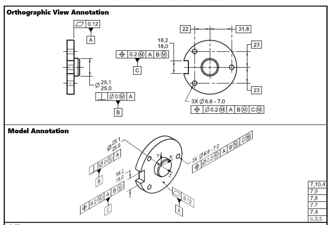
Flatness in Geometric Dimensioning and Tolerancing (GD&T) is a 2D surface tolerance that ensures a surface does not deviate from a perfectly flat plane by more than a specified amount. Indicated by two parallel lines in a feature control frame on a technical drawing, flatness tolerance means that the entire defined surface must lie between two parallel planes whose separation distance equals the flatness tolerance value. This tolerance does not relate to any datum plane and is critical for surfaces requiring a high degree of flatness for functional reasons, such as sealing surfaces or contact faces for assembly.
Flatness Symbol in Drawing
The flatness symbol in GD&T (Geometric Dimensioning and Tolerancing) is represented by two parallel lines. When this symbol appears on a technical drawing, it specifies that the feature associated with the symbol must lie between two parallel planes where the distance between these planes is the flatness tolerance.
Here’s how the flatness symbol generally appears within a feature control frame on a technical drawing:
┌───────┐
│ │
│ // │ <── Flatness Symbol
│ 0.05 │
└───────┘
In the feature control frame shown above, the flatness symbol (//) is located at the top, and the tolerance value (e.g., 0.05 mm or inches) is indicated below it. This frame is typically linked to or placed near the surface on the drawing to which the flatness tolerance applies.
Flatness Drawings
To show flatness on a technical drawing, you would use a feature control frame (FCF) and the flatness symbol, which consists of two parallel lines. This FCF is attached to the surface for which the flatness tolerance is specified.
Here are some examples of how to show the straightness of the technical drawing:
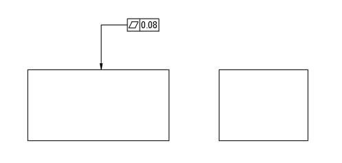
Flatness of a block
The figure below indicates flatness specified on the top surface of a plate. In this case, the tolerance zone is between two parallel circular planes with an interval of the tolerance value. The actually measured surface must be within this 0.08 interval of the two parallel planes.
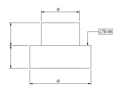
Flatness of an axial part
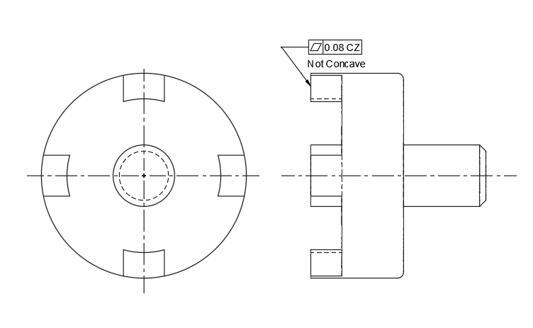
The figure below indicates flatness specified on the plane of a stepped axial part. In this case, the tolerance zone is between two parallel circular planes with an interval of the tolerance value. The axial portion not subject to flatness tolerance is excluded from the tolerance zone. The measured surface must be within the 0.08 interval of the two parallel circular planes.
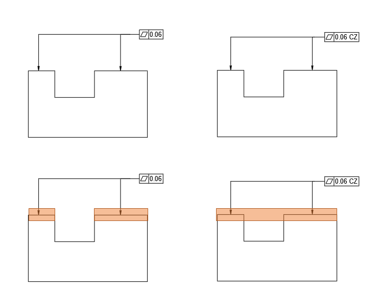
Flatness CZ
CZ stands for Common Zone. Without CZ, each plane is considered independently. But with CZ, the two planes must be parallel to each other and within a common zone.
Flatness NC
NC stands for Not Convex. Convex means raised or domed shaped. By putting Not in front, it means the center cannot be higher. The circular area at the center must always be lower than the four islands outside.
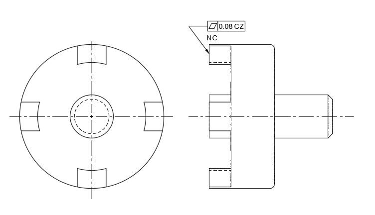
Flatness Not Concave
Concave means recessed or concave shaped. By putting Not in front, it means the center cannot be lower. The circular area at the center must always be lower than the four islands outside.
Flatness Tolerance Standard
Common tolerances for flatness in machining and manufacturing processes can vary widely depending on the material, the size of the surface, the type of process used, and the part’s intended application. There is no one-size-fits-all table for flatness tolerances because they are highly dependent on specific industry requirements and the capabilities of the manufacturing process being used.
However, for illustrative purposes, below is a generic table giving a rough idea of flatness tolerances that might be expected for machined surfaces. These figures are for general guidance only and may not be appropriate for all situations.
| Surface Size (Length/Width) | Flatness Tolerance (Typical Range) |
| Up to 100 mm (4 in) | 0.005 – 0.05 mm (0.0002 – 0.002 in) |
| 100 to 300 mm (4 to 12 in) | 0.02 – 0.1 mm (0.0008 – 0.004 in) |
| 300 to 1000 mm (1 to 3 ft) | 0.05 – 0.25 mm (0.002 – 0.01 in) |
| Over 1000 mm (Over 3 ft) | 0.1 mm and up (0.004 in and up) |
For high-precision applications (like aerospace or medical devices), tolerances may be tighter, while for less critical applications (like construction or commercial products), tolerances may be more relaxed.
Always consult relevant manufacturing standards, material specifications, and design requirements when selecting the appropriate flatness tolerance for a given part. For critical applications or when in doubt, it’s best to work directly with experienced engineers or refer to industry-specific handbooks and guidelines.
GD&T Flatness CZ (Common Zone)
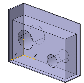
The flatness common zone refers to a uniform tolerance zone in geometric dimensioning and tolerancing (GD&T) where the entire surface of a part must lie within two parallel planes separated by a specified tolerance value. Unlike local flatness, which might only evaluate individual regions, the common zone ensures the flatness requirement is applied across the entire surface as a whole. This means all points on the surface must remain within the defined zone, ensuring a consistent and precise flatness that is critical for proper assembly and functionality in precision manufacturing.
Flatness Tolerance Zone:
- The tolerance zone is defined by two parallel planes. The distance between these planes is the flatness tolerance.
- The surface must remain entirely within this zone.
Flatness Common Zone Meaning:
- A common zone implies that the flatness requirement applies to the entire surface as a whole, instead of being segmented or applied to individual sections.
Example:
If a flatness tolerance is specified as 0.05 mm, the entire surface must stay within two parallel planes that are 0.05 mm apart. A common zone ensures that this tolerance is applied to the entire surface, rather than different zones or localized regions.
Flatness Measurement (Tools & How To Measure)
Measuring flatness typically requires specialized tools to determine how much a surface deviates from being perfectly flat. Here are some common tools used for flatness measurement:
1. Surface Plate: A highly precise, flat reference surface (usually made of granite). Parts are placed on the surface plate, and deviations are checked using other tools like dial indicators or feeler gauges.
2. Dial Indicator: A mechanical device with a plunger that detects variations in the surface. It is mounted on a stable base or height gauge, the dial indicator moves across the surface, and deviations are noted.
3. Straight Edge: A long, flat bar used as a reference for flatness. It gaps between the straight edge and the surface can be checked visually or with feeler gauges.
4. Feeler Gauges: Thin metal strips of known thickness used to measure gaps between a surface and a reference (e.g., a straight edge or surface plate).
5. Laser Scanners: Advanced tools that use laser technology to measure flatness by scanning the surface and creating a digital map of deviations.
6. Coordinate Measuring Machine (CMM): A precision instrument that uses probes to measure the surface at multiple points. It provides highly accurate 3D measurements of flatness.
7. Autocollimator: An optical device that measures small angular deviations on a reflective surface. Useful for checking large surfaces for flatness.
8. Flatness Gauges: Specialized tools designed specifically to measure flatness, often incorporating sensitive electronics for high precision.
Difference Between Flatness and Straightness in GD&T
Flatness and straightness are both types of geometric tolerances used in GD&T (Geometric Dimensioning and Tolerancing) to control the form of a feature without reference to any other feature. However, they apply to different aspects of a part’s geometry:
Flatness:
- Applies to a surface.
- Ensures that all points on a specified surface lie between two parallel planes.
- The tolerance zone is defined by two parallel planes within which the entire surface must lie.
- It is a 2D tolerance and does not pertain to an axis.
- Flatness tolerance does not depend on the part’s orientation or any datum features.
Straightness:
- Applies to a line or axis.
- Ensures that a feature or line is straight within a specified tolerance.
- The tolerance zone can be a cylindrical zone within which the entire line element or axis must lie.
- It can be a 2D or 3D tolerance, controlling the straightness of a line on a surface (2D) or the straightness of an axis (3D).
- When applying straightness to an axis, it may or may not relate to datums, depending on whether it’s controlling the median line (no datum reference) or the feature’s orientation (datum reference might be used).
Flatness is concerned with the overall plane being even and flat, while straightness is concerned with an individual line or axis being straight. An easy way to remember the difference is that flatness is about a surface (like a table top), and straightness is about a line or edge (like a ruler or shaft).
Related Articles:
 Guide to Straightness – Straightness Definition, Measurement & Difference Between Flatness and Parallelism | CNCLATHING
 GD&T Profile Tolerance: Basic Knowledge, Types, Symbol, Calculation, Uses
 GD&T Angularity Definition, Symbol, Callout, Measurement, Tolerance & Angularity vs Profile
 GD&T MMC: Definition, Formula, Calculation, Bonus Tolerance, Uses, MMC vs LMC
 GD&T Tolerance Definitions: 14 Different Tolerances Specific to GD&T Use
 Surface Roughness Symbols, Grade Numbers, Indication, Terminology and Calculation | CNCLATHING