
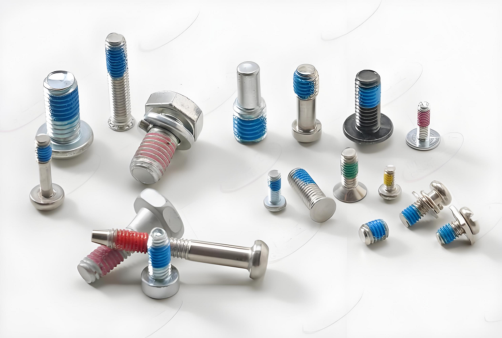
Fasteners refer to components that serve the function of securing objects together. Threaded fasteners, which contain threads and are manufactured to precise dimensions, exert their fundamental function through the interaction between external and internal threads. This capability allows threaded fasteners to play a significant role in the connection and fastening of objects, as well as in facilitating movement.
I. What are Threaded Fasteners?
Fasteners are universal components used for mechanical connection, fixation, or sealing. They securely join two or more parts through physical constraints (e.g., thread engagement, frictional locking) to ensure structural stability and detachability. Common types include bolts, nuts, screws, and rivets, widely applied in mechanical manufacturing, construction engineering, automotive assembly, and other fields. Their performance directly impacts equipment safety and service life.
1.1 Types of Threaded Fasteners
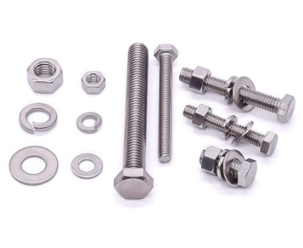
Threaded fasteners are primarily categorized into:
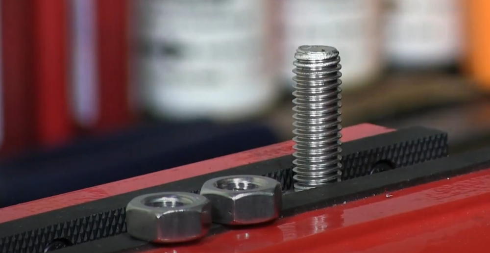
- Bolts – Externally threaded fasteners designed to be used with nuts.
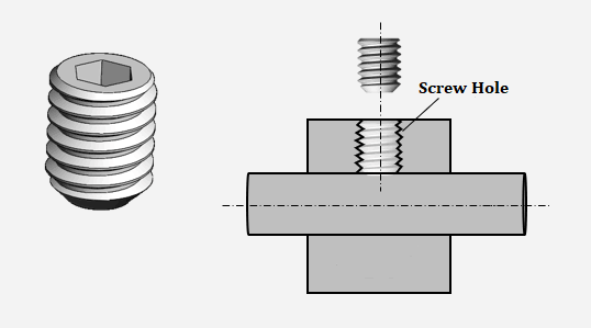
- Screws – Externally threaded fasteners that engage directly with a pre-threaded hole or create their own threads in a material.
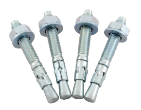
- Studs – Threaded rods that are externally threaded on both ends and used for high-strength connections.
- Nuts – Internally threaded components that mate with bolts or studs to create a secure joint.
- Threaded Inserts – Components inserted into materials to provide strong internal threads.
II. Fastener Threads and Types
2.1 Fastener Thread Types (by Purpose)
Threads can be classified into four categories based on their intended application:
- Fastening Threads – Includes standard threads, transitional fit threads, interference fit threads, fine threads, and MJ threads.
- Transmission Threads – Includes trapezoidal threads, sawtooth threads, and square threads.
- Pipe Threads – Includes 55° and 60° pipe threads, metric tapered threads, and dry-seal pipe threads.
- Special Threads – Includes threads used in optical instruments, short trapezoidal threads for forged steel valves, machine tool trapezoidal screw threads, petroleum threads, and gas cylinder threads.
2.2 Fastener Thread Geometric Parameters
Threads are defined by five geometric parameters:
- Thread profile
- Diameter
- Pitch
- Number of threads (single-start or multi-start)
- Thread direction (right-hand or left-hand)
Only internal and external threads that fully match these five elements can be properly engaged. Among these, the thread profile, nominal diameter, and pitch are the three most critical elements.
International standards specify certain standardized thread profiles, nominal diameters, and pitches. Threads that conform to these specifications are classified as standard threads. If the thread profile meets the standard but the nominal diameter or pitch does not, it is a special thread. If the thread profile itself does not conform to the standard, it is considered a non-standard thread.
2.3 Thread Profiles & Standards
The profile shape of a thread, when viewed in a cross-section along the thread axis, is referred to as the thread profile. It can take various forms such as:
- Triangular (standard fastening threads)
- Trapezoidal (power transmission threads)
- Sawtooth (unidirectional load-bearing threads)
- Square (high-efficiency power transmission threads)
2.3.1 Standard Thread (M) – ISO 68-1
The most commonly used connecting thread, with a triangular profile and a 60° angle. The feature code for standard threads is M. Standard threads are divided into coarse and fine threads, which share the same code. Generally, coarse threads are used for connections. When the major diameter is the same, the pitch and profile height of fine threads are smaller than those of coarse threads, making fine threads suitable for thin-walled part connections.
2.3.2 Unified Thread Standard (UNC, UNF, UNEF) – ANSI/ASME B1.1
A widely used thread system in North America, similar to metric threads but with different thread pitches and diameters. Includes Unified Coarse (UNC), Unified Fine (UNF), and Unified Extra Fine (UNEF) threads.
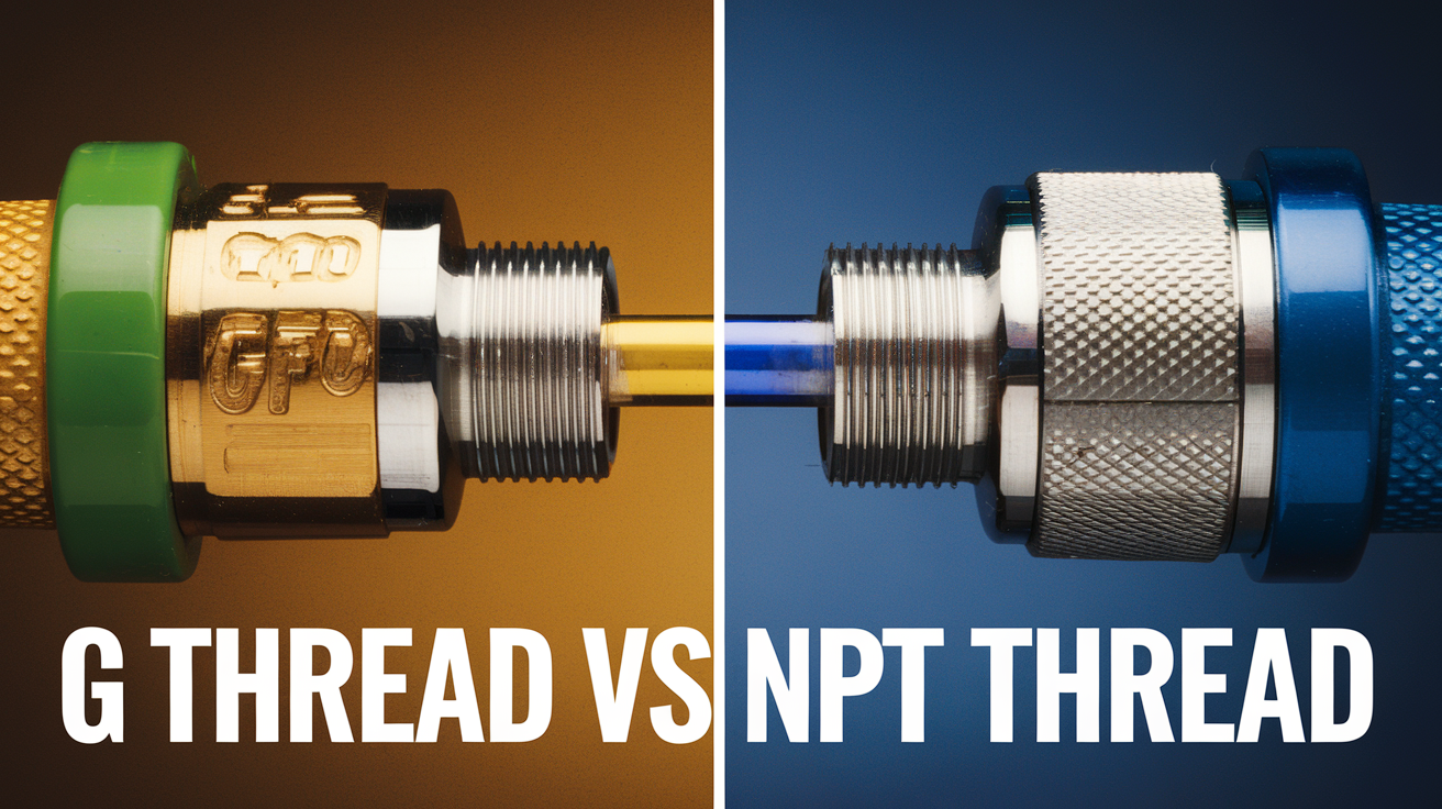
2.3.3 Pipe Threads (G, R, Rp, Rc) – ISO 7-1, ANSI/ASME B1.20.1
Primarily used for connecting pipes, with a triangular profile and a 55° angle. There are two types of pipe threads:
- Non-sealing pipe threads (e.g., G-thread, BSPP) – Denoted as G, with both internal and external threads being cylindrical and incapable of sealing, commonly used in connections for conduits that do not require sealing.
- Sealing pipe threads (e.g., NPT, BSPT, Rp, Rc) – With three codes: tapered external threads (R), tapered internal threads (Rc, with a taper of 1:16), and cylindrical internal threads (Rp). These threads can connect tapered internal and external threads or cylindrical internal and tapered external threads, providing sealing capability, commonly used in water pipes, gas pipes, and oil pipes.
2.3.4 Trapezoidal Threads (Tr) – ISO 2901
A commonly used transmission thread with an isosceles trapezoidal profile and a 30° angle, denoted as Tr.
2.3.5 Sawtooth Threads (B) – ISO 103
A type of transmission thread that bears force in one direction, with an unequal trapezoidal profile, one side having a 30° angle and the other a 3° angle, denoted as B.
2.4 Thread Dimensions
Threads are characterized by three key diameters:
- Major Diameter (D or d) – The outermost diameter of the thread.
- Minor Diameter (D1 or d1) – The innermost diameter of the thread.
- Pitch Diameter – The theoretical diameter where the thread thickness is equal to the space between threads.
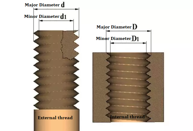
The major diameter for external threads corresponds to the nominal diameter, while for internal threads, the minor diameter is considered.
2.5 Thread Direction
Threads can be divided into left-hand and right-hand. Threads that are screwed in clockwise are called right-hand threads, and threads that are screwed in counterclockwise are called left-hand threads. Right-hand threads are commonly used in engineering.
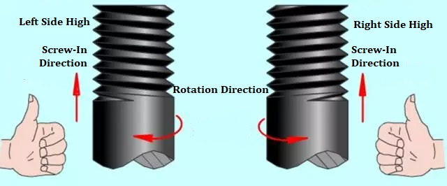
Left-hand thread Right-hand thread
2.6 Number of Thread Lines
Threads can be divided into single-line and multi-line. Threads formed along one spiral line are called single-line threads, and threads formed along more than two spiral lines are called multi-line threads.
Most connecting threads are single-line.
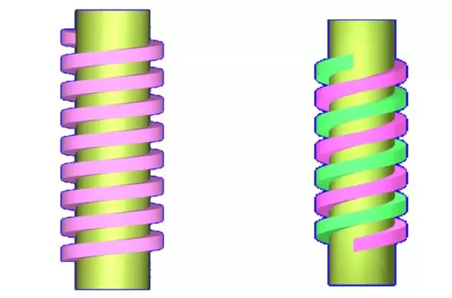
Single-line thread (left) Double-line thread (right)
2.7 Thread Pitch and Lead
The axial distance between two corresponding points on the median diameter line of two adjacent teeth of a thread is called the pitch. The axial movement distance of one rotation along the same spiral line is called the lead. The lead of a single-line thread is equal to the pitch, and the lead of a multi-line thread is equal to the pitch x the number of lines.
2.8 Threaded Fastener Symbols & Marking Method
For example: M 10×1 LH –7H-L
- M represents the common thread feature code;
- 10×1 represents the nominal diameter×pitch, and the pitch is not indicated for coarse threads;
- LH represents the left-hand thread code, and the right-hand thread does not indicate the direction of rotation code;
- 7H represents the tolerance zone code;
- L represents the screw length group code. The group code is not indicated for medium length, and the specific length value is indicated when special needs are required.
2.9 Thread Fit Classes
Thread fit refers to the degree of tightness between internal and external threads. The ISO metric thread fit system (ISO 965-1) and the Unified Thread Standard (ANSI/ASME B1.1) define the following fit classes:
ISO Metric Threads:
- External threads: 4h, 6h, 6g
- Internal threads: 5H, 6H, 7H
- Common fit combinations include 6H/6g (standard fastening applications) and H/g or H/h for coated threads.
The higher the grade number, the tighter the fit. In the imperial thread, the deviation is only specified for 1A and 2A grades, the deviation for 3A is zero, and the grade deviations for 1A and 2A are equal.
The larger the grade number, the smaller the tolerance, as shown in the figure:
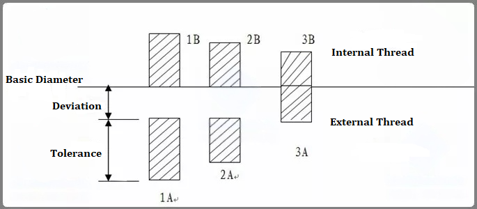
Unified Thread Standard (Imperial Threads):
- External threads: 1A, 2A, 3A
- Internal threads: 1B, 2B, 3B
- 2A/2B fit is the most commonly used, while 3A/3B provides a tighter fit for high-precision applications.
In metric threads, the basic deviation of H and h is zero. The basic deviation of G is positive, and the basic deviations of e, f and g are negative.
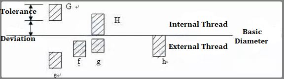
- H is the common tolerance zone position for internal threads, which is generally not used for surface coating or extremely thin phosphating layer. The basic deviation of G position is used for special occasions, such as thicker coating, which is rarely used.
- G is often used to plate thin coatings of 6-9um. For example, if the product drawing requires a 6h bolt, the thread before plating uses a 6g tolerance zone.
- The thread fit is best combined into H/g, H/h or G/h. For refined fastener threads such as bolts and nuts, the standard recommends the use of 6H/6g fit.
2.10 Threaded Fastener Materials
Types of Common Fastener Materials
Currently, standard fasteners in the market are mainly made from four materials: carbon steel, stainless steel, brass, and aluminum alloy.
- Carbon Steel (ISO 898-1, ASTM A307, ASTM F568): Classified based on carbon content into low carbon steel, medium carbon steel, high carbon steel, and alloy steel.
- Low Carbon Steel (C ≤ 0.25%): Commonly referred to as A3 steel in China. Mainly used for grade 4.8 bolts, grade 4 nuts, and small screws that do not require hardness.
- Medium Carbon Steel (0.25% < C ≤ 0.60%): Commonly referred to as 35# or 45# steel in China. Mainly used for grade 8 nuts and grade 8.8 bolts.
- High Carbon Steel (C > 0.60%): Currently, it is rarely used in the market.
- Stainless Steel (ISO 3506, ASTM F593): Mainly divided into austenitic (18% Cr, 8% Ni). Advantages include good heat resistance, corrosion resistance, and weldability.
- Austenitic Stainless Steel (A2, A4, 18-8, 316, etc.) – Provides superior corrosion resistance.
- Brass & Copper Alloys (ASTM B16, ASTM B36): Common materials include brass and zinc-copper alloys.
- Commonly used for decorative and electrical applications.
- Alloy Steel (ISO 898-1, ASTM A193, ASTM A320): Generally refers to chromium-molybdenum alloy steel.
- Includes chrome-molybdenum steel (SCM435, 42CrMo4, etc.) for high-strength fasteners.
Commonly Used Materials for Fasteners
- Materials for Bolts, Studs, Screws:
- For grades 3.6, 4.6, 4.8, 5.6, 5.8, and 6.8, carbon steel is generally used without heat treatment.
- For grades 8.8 and 9.8, low carbon alloy steel or medium carbon steel is typically used, with quenching and tempering.
- For grade 10.9, low or medium carbon alloy steel or alloy steel is used, with quenching and tempering.
- For grade 12.9, alloy steel is used, also with quenching and tempering.
- Materials for Nuts:
- For grades 4, 5, and 6, carbon steel is generally used without heat treatment.
- For grades 8 and 9, medium carbon steel is used, with quenching and tempering.
- For grades 10 and 12, alloying elements are added to improve mechanical properties, with quenching and tempering.
- Material Composition:
- Carbon (C): Increases the strength of steel, especially its heat treatment performance; however, increased carbon content decreases plasticity and toughness, affecting cold heading and welding performance.
- Manganese (Mn): Increases strength and, to some extent, improves hardenability, enhancing the hardness penetration during quenching. However, excessive manganese can negatively impact ductility and weldability, and affect the control of plated coatings.
- Nickel (Ni): Enhances strength, improves toughness at low temperatures, increases atmospheric corrosion resistance, ensures stable heat treatment effects, and reduces hydrogen embrittlement.
- Chromium (Cr): Improves hardenability, enhances wear resistance, increases corrosion resistance, and helps maintain strength at high temperatures.
- Molybdenum (Mo): Helps control hardenability, reduces sensitivity to temper brittleness, and significantly improves tensile strength at high temperatures.
- Boron (B): Enhances hardenability and aids in achieving the desired response from low carbon steel during heat treatment.
- Vanadium (V): Refines austenitic grain size and improves toughness.
- Silicon (Si): Ensures the strength of steel; appropriate content can improve plasticity and toughness.
- Sulfur (S): Improves machinability but can cause hot brittleness, deteriorating steel quality. Increased sulfur content can adversely affect weldability.
- Phosphorus (P): Provides solid solution strengthening and cold work hardening effects. When used with steel, it enhances atmospheric corrosion resistance in low-alloy high-strength steel but reduces impact performance. It can improve machinability when combined with sulfur and manganese, increasing temper brittleness and cold brittleness sensitivity.
III. Threaded Fastener Manufacturing Process
So now we introduce how the fastener be manufactured:
3.1 Threaded Fastener Production Process Flow
- Raw Material Preparation -> 2. Annealing & Heat Treatment -> 3. Acid Washing & Phosphating -> 4. Wire Drawing -> 5. Cold Heading (Forging) -> 6. Thread Rolling or Cutting -> 7. Surface Coating & Plating -> 8. Final Inspection & Packaging
3.2 Overview of Fastener Manufacturing Processes
3.2.1 Coil Wire
Coil wire, also known as wire rod or coil material, is produced by heating and rolling steel billets. (Hot-rolled coils cannot be used for fastener production due to their size and surface quality and must undergo further processing.)
3.2.2 Annealing
Annealing: A metal heat treatment process that involves slowly heating the metal to a certain temperature, maintaining it for a sufficient time, and then cooling it at an appropriate rate (usually slowly, sometimes controlled). The purpose is to soften materials or workpieces that have been cast, forged, welded, or machined, improving plasticity and toughness, homogenizing the chemical composition, removing residual stress, and achieving the desired physical properties.
There are various annealing processes depending on the purpose, such as recrystallization annealing, isothermal annealing, homogenization annealing, spheroidizing annealing, stress relief annealing, recrystallization annealing, stabilization annealing, and magnetic field annealing.
Spheroidizing annealing—This process rounds the carbides, giving the material plasticity. Steel is heated to 20–30°C above Ac1, held for a period, and then slowly cooled to obtain a structure with uniformly distributed spherical or granular carbides in the ferrite matrix.
When steel is cooled after rolling or forging, it typically forms a lamellar pearlite structure with network cementite, which is hard and brittle, making it difficult to machine and prone to deformation and cracking during subsequent quenching. In contrast, spheroidizing annealing results in a globular pearlite structure, where the cementite forms spherical particles dispersed in the ferrite matrix, which is easier to machine and less prone to deformation and cracking during quenching.
Verification of spheroidized structure and decarburization layer is necessary to confirm the spheroidizing effect.
3.2.3 Acid Washing, Phosphating, and Soaping
Equipment: Acid washing tank, water washing tank, phosphating tank, soaping tank.
Purpose of Acid Washing: To remove the oxidation film and rust from the surface of the wire material.
Purpose of Phosphating: To form a layer of phosphate film on the metal surface to reduce abrasion on tools during drawing and forming processes, providing lubrication. It also serves a certain rust prevention function.
Purpose of Soaping: To provide lubrication.
Purpose of Water Washing: To prevent acid solutions from contaminating the next tank.
Surface Condition Inspection: Phosphate film, scratches, marks, oxidation.
3.2.4 Wire Drawing
Equipment: Wire drawing machine, wire drawing die.
Purpose of Wire Drawing: To provide wire of appropriate specifications for cold heading production. Wire drawing is a pressure processing method where a wire rod undergoes plastic deformation through a die under a certain tensile force, resulting in decreased cross-section and increased length.
Inspection: Material diameter and surface condition.
3.2.5 Cold Heading
Equipment: Cold heading machine, cold heading die.
Cold heading is a forging method that uses molds to shape metal rods at room temperature. It is commonly used to manufacture screws, bolts, rivets, and nuts, minimizing or replacing cutting processes. The material utilization rate in cold heading can reach 80–90%. It is usually performed on specialized cold heading machines, facilitating continuous, multi-station, automated production. The cold heading machine sequentially completes cutting, heading, accumulating, shaping, chamfering, threading, reducing diameter, and trimming processes, resulting in high production efficiency. The rod is automatically fed into the machine, cut into blanks, and then sequentially transferred to the accumulating and punching stations for cold heading.
3.2.6 Turning
Turning is a type of machining that primarily uses lathe equipment to shape the workpiece blank into the desired external profile. Turning includes processes like turning, drilling, and milling.
3.2.7 Thread Forming
Equipment: Thread rolling machine, thread rolling wheels, tapping machine, taps, etc.
Thread Forming Methods: Rolling threads, cutting threads, and tapping. Rolling and cutting are primarily used for manufacturing external threads, while tapping is used for internal threads. Rolling and cutting threads are achieved through material extrusion, while tapping involves either extrusion or cutting to create internal threads.
3.2.8 Heat Treatment
Heat treatment is a comprehensive process that involves heating, holding, and cooling materials in a specific medium to change their surface or internal structure to control their properties.
The main purpose of heat treatment for fasteners is to achieve good overall mechanical properties through quenching and tempering.
Annealing involves heating the workpiece to an appropriate temperature, maintaining it for a specific time based on material and dimensions, and then slowly cooling to achieve a balanced internal structure for good processing and performance, or to prepare for further quenching.
Normalizing consists of heating the workpiece to a suitable temperature and then cooling it in air. The effect is similar to annealing, but the resulting structure is finer, commonly used to improve the cutting performance of materials or as a final heat treatment for less critical parts.
Quenching involves heating the workpiece and then rapidly cooling it in water, oil, or other inorganic salts or organic solutions. This process hardens the steel but also makes it brittle.
Tempering is performed to reduce brittleness by holding the quenched steel at a temperature above room temperature but below 650°C for a prolonged period before cooling. This process is known as tempering.
The four main processes in heat treatment are annealing, normalizing, quenching, and tempering, with quenching and tempering closely related and often used together.
3.2.9 Surface Treatment
Surface treatment is a process that forms a layer on the surface of the base material that has different mechanical, physical, and chemical properties. The purpose of surface treatment is to meet product requirements for corrosion resistance, wear resistance, decoration, or other special functions.
- Electroplating
Electroplating (zinc, nickel, copper, chromium, zinc-nickel alloys, etc.) is a process that uses electrolysis to deposit a thin layer of metal or alloy onto certain metal surfaces, preventing corrosion, enhancing wear resistance, electrical conductivity, reflectivity, and improving appearance.Main Uses of Electroplating:- To enhance the corrosion resistance of metal products or parts, e.g., zinc plating on ferrous products.To improve the protective and decorative performance of metal products, e.g., copper, nickel, or chromium plating on steel products.To repair the dimensions of worn metal parts, e.g., using iron or chromium plating to restore the dimensions of critical mechanical parts like shafts and gears.To impart specific functions to products or parts, e.g., hard chromium plating can improve wear resistance.
- Degreasing → Water Washing → Acid Washing → Phosphating → Drying → Galvanizing → Post-treatment → Passivation.
- Oxidation
Oxidation, also known as blackening or bluing, is a process where a blue or black oxide layer is formed on the surface of a workpiece in air, steam, or chemical solutions at room temperature or elevated temperatures to improve corrosion resistance and appearance.In mechanical manufacturing, a heated NaOH solution is commonly used to blacken workpieces, which is cost-effective compared to zinc or chromium plating.The black oxide layer formed has a thickness of 0.5-1.5μm and provides lower corrosion resistance compared to other chemical coatings. - Dacromet
Dacromet, also known as zinc-aluminum-chromium coating, is a new type of corrosion-resistant coating composed mainly of zinc powder, aluminum powder, chromic acid, and deionized water.The Dacromet solution is prepared into a water-soluble coating and then directly applied to the clean surface of the workpiece, followed by baking to form a Dacromet layer.Dacromet Coating Process:- Organic solvent degreasing → Mechanical shot blasting → Spraying → Baking → Secondary spraying → Baking → Tertiary spraying → Baking and drying.
- Exceptional corrosion resistance: The Dacromet layer is only 4-8μm thick, but its rust prevention effect is 7-10 times greater than that of traditional zinc plating, hot-dip galvanizing, or coating methods. Standard parts treated with Dacromet have passed salt spray tests for over 1200 hours without showing red rust.No hydrogen embrittlement: The Dacromet treatment process eliminates hydrogen embrittlement, making it suitable for stressed components.High heat resistance: Dacromet can withstand high-temperature corrosion, withstanding temperatures above 300°C. In contrast, traditional galvanizing starts to peel off at 100°C.Good adhesion and re-coating properties: The Dacromet coating has excellent adhesion to the metal substrate and shows strong adhesion to other additional coatings, making it easy to apply color coatings, with adhesion exceeding that of phosphating films.Good permeability: Due to the electrostatic shielding effect, deep holes, narrow seams, and inner walls of pipes are difficult to coat with zinc using electroplating. Dacromet can penetrate these areas to form a protective layer.No pollution: The entire process of Dacromet production and application does not generate wastewater or gas pollutants, eliminating the need for waste treatment and reducing processing costs.
- It contains chromium ions harmful to the environment and human health, especially hexavalent chromium, which is carcinogenic.
- Dacromet has a high sintering temperature and long processing time, leading to high energy consumption.
- Dacromet coatings have low surface hardness and wear resistance, and the products with Dacromet coatings are not suitable for contact with or connection to parts made of copper, magnesium, nickel, or stainless steel, as this can lead to contact corrosion, affecting surface quality and corrosion resistance.
- Dacromet coatings have a limited color range, being only silver-white and silver-gray, which may not meet the personalization needs of automotive development. However, different colors can be achieved through post-treatment or composite coatings to enhance the decorative and matching qualities of heavy-duty automotive components.
- Dacromet coatings have poor electrical conductivity, making them unsuitable for electrically conductive connections, such as grounding bolts in electrical appliances.
3.2.10 Typical Processing Routes
- Small Specification Bolts Below Grade 8.8 (M16 and below)
- Raw Material Selection: Low carbon steel (Q235, 08, 10, 18, etc.)
- Blank Shaping Method: Cold heading
- Thread Forming: Rolling or cutting threads
- Process Route: Raw material selection → Material modification → Cold heading → Machining (chamfering, flat end) → Rolling or cutting threads → Surface treatment (as required) → Final inspection → Packaging
- Large Specification Bolts Grade 12.9 (M16 and above)
- Raw Material Selection: Medium carbon alloy steel (35CrMo, 42CrMo, SCM435, etc.)
- Blank Shaping Method: Hot heading
- Thread Forming: Rolling threads
- Process Route: Raw material selection → Material modification → Cutting → Machining (turning the blank) → Hot heading → Machining (turning the head, chamfering, flat end) → Marking → Shot blasting → Grinding (grinding the blank) → Rolling threads → Phosphating → Heat treatment → Flaw detection → Surface treatment → Final inspection → Packaging
- Nut Processing
- Using Hot Heading for Large Specification Nuts
- Material Selection: According to the performance requirements of the nut
- Process Route: Material modification → Cutting → Hot heading → Machining (mainly turning the thread base, ensuring height) → Marking → Tapping → Heat treatment → Surface treatment → Final inspection → Packaging.
IV. Thread Fastener Inspection and Testing
Fastener inspection and testing are critical processes to ensure compliance with mechanical, dimensional, and chemical standards. These tests verify strength, durability, corrosion resistance, and overall quality, enabling fasteners to meet stringent safety and performance requirements in various industries.
4.1 General Inspection
4.1.1. Verification of Technical Documents and Quality Certificates
Before conducting physical tests, inspectors must verify that the technical documentation and material certificates conform to the specified ISO, ASTM, or ANSI standards.
4.1.2. Visual Inspection
All fasteners must have proper markings to indicate their grade, manufacturer, and batch number. Requirements include:
- a. Bolts and screws with a performance grade ≥ 4.8 must be marked.
- b. Nuts with a performance grade ≥ 5 must be marked.
- c. Bolts, screws, and nuts with a nominal diameter ≥ 5mm need to be marked.
- d. Bolts and screws with a nominal diameter ≥ 30mm must have the production batch number marked on the identification surface.
- e. Washers with a hardness of 300HV should have relevant markings (recommended).
The appearance of fasteners should be clean, smooth, free from burrs, rust spots, missing teeth, or damaged teeth. The coating should not have defects such as bubbles or peeling, and the coating thickness must meet standard requirements.
4.2 Dimensional Inspection
Fasteners must conform to ISO 4759-1, ANSI/ASME B18.2.1, ASTM F606 or other applicable standards for dimensional accuracy. So Conduct inspections based on relevant national standards or technical requirements (agreements, specifications, and drawings).
Inspection Parameters
- For bolts, screws, studs, and nuts, check thread length, nominal diameter, head thickness, shaft diameter, nut height, and straightness using appropriate thread gauges.
- Use a 6g ring gauge for pre-plating bolts and screws, and a 6h ring gauge for post-plating inspection.
- Use a 6G ring gauge for pre-plating nuts, and a 6H plug gauge for post-plating inspection.
- For pass gauges, every thread should pass smoothly to be considered qualified; for stop gauges, passing a maximum of 2 threads is acceptable.
4.3 Strength and Plasticity Performance Test
- Strength: The ability of metal materials to resist plastic deformation and fracture under external forces.
- Plasticity: The ability of metal materials to undergo permanent deformation without breaking under external forces.
Tensile Test (ISO 6892-1, ASTM F606, ANSI B18.3)
The testing machine grips both ends of the test rod and separates them at a speed not exceeding 10mm/min until the rod breaks, recording relevant data.
Sample Preparation
- Specimens: Finished product or heat-treated semi-finished product.
- Sampling location: 1/4 of the thread diameter.
- Standard test rod specifications as per ISO 6892-1.
Testing Equipment
- Universal tensile testing machine with precision load sensors.
Test Results & Acceptance Criteria
- Tensile Strength (Rₘ):
- Formula: Rₘ = Fₘ / S₀
- For Grade 10.9 bolts, the minimum requirement is Rₘ ≥ 1040 MPa.
- Yield Strength (ReHR_{eH}ReH, ReLR_{eL}ReL):
- Formula: Rₑₕ = Fₑₕ / S₀ (Upper yield strength), Rₑₗ = Fₑₗ / S₀ (Lower yield strength)
- For grade 10.9 high-strength bolts, the requirement is Rₑₗ ≥ 940 MPa.
- Elongation after Fracture (A%):
- Formula: A = (L₁ – L₀) / L₀
- For Grade 10.9 high-strength bolts, the requirement is A ≥ 9%.
- Reduction of Area (Z%):
- Formula: S = (d₀ – d₁) / d₀
- For Grade 10.9 high-strength bolts, the requirement is Z ≥ 48%.
4.4 Toughness Performance Test
Toughness indicates the ability of a material to absorb energy during plastic deformation and fracture. Better toughness reduces the likelihood of brittle fracture.
Testing Method: Low-Temperature Impact Test
- Sample: Finished product or heat-treated semi-finished product.
- Sampling Ratio: 8 samples per batch.
Sample Preparation:
- Sample: Near-surface sampling.
- Sample Size: Standard dimensions (Length 55mm, Cross-section 10mm x 10mm, with a V-shaped or U-shaped notch in the middle).
- Testing Equipment: Pendulum impact testing machine.
- Testing Method: Place the cooled sample (to -45°C) with the designated notch geometry between the supports of the testing machine, with the notch facing away from the striking surface. Strike the sample once with the pendulum and measure the absorbed energy. Requirement: AKV2≥27JA_{KV2} ≥ 27 JAKV2≥27J.
4.5 Hardness Performance Test
The ability of a material to resist the penetration of a hard object into its surface, which is an indicator of the softness or hardness of metal materials.
Hardness Testing Standards: Brinell Hardness (ISO 6506, ASTM E10), Rockwell Hardness (ISO 6508, ASTM E18), Vickers Hardness (ISO 6507, ASTM E92)
Testing Equipment & Principle (Rockwell): Under a sequence of initial and total test forces, a specified indenter (HRC 120-degree diamond cone) is pressed into the sample surface. After maintaining a certain time, the main test force is removed, and the residual depth of the indentation is measured while keeping the initial test force. This depth indicates the level of Rockwell hardness.
Results Calculation:
- Apply initial test force F0F_0F0 and measure initial displacement h0h_0h0.
- Apply the main test force F1F_1F1, maintain for a certain time, and measure displacement h1h_1h1 after removing the main test force.
- Maintain initial test force F0F_0F0 and measure displacement h2h_2h2.
4.6 Wedge Load Test (ISO 898-1, ASTM F606)
Wedge load is applied during bolt tensile testing, adding a wedge pad below the bolt head to primarily assess the connection performance between the bolt head and the shaft. The bolt head should not fracture when the tensile load reaches its maximum value. The wedge pad can have angles of 4, 6, or 10 degrees, depending on standard specifications.
Testing Method: A wedge pad (4°, 6°, or 10°) is placed under the bolt head. The bolt is pulled in tension at 25mm/min.
Pass/fail criteria: The bolt head must not separate from the shaft before reaching the required tensile strength.
4.7 Nut Proof Load Test (ISO 898-2, ASTM F606)
The guarantee load of a nut refers to the specified tensile or compressive load under which the threads should not fail or deform, and the nut can be manually unscrewed from the test core rod after the test.
Testing Method: Insert the nut specimen into the core rod, implement axial tensile tests using a testing machine, ensuring the separation rate does not exceed 3mm/min, apply the specified guarantee load, maintain for 15 seconds, then unload and remove the nut.
Judging Standard: The nut should not break, and the threads should not disengage (can be unscrewed by hand; if a wrench is needed, it should not exceed half a turn).
Guarantee Load Calculation:
Guarantee Load = Guarantee Stress (Sp) × Stress Cross-Sectional Area
Example for M64 nut:
Load = 1060 N/mm² × 2680 mm² = 2840800 N
4.8 Chemical Composition Analysis (ISO 17025, ASTM E415, ASTM E1086)
Testing Equipment: Optical emission spectrometer.
Principle: Various elements emit their characteristic spectra when excited at high temperatures and energies. The optical emission spectrometer determines the chemical composition and approximate content of metals based on the characteristic spectra produced when the elements are excited.
Sample Requirements:
- No defects such as sand holes, small pores, or segregation.
- The sample surface must be flat and should completely cover the excitation hole.
- The sample surface must be clean and uncontaminated, free from other substances, and not touched by hands.
V. International Standards for Threaded Fasteners
6.1 ISO Standards
- ISO 898-1 – Mechanical properties of bolts and screws.
- ISO 965-1 – General thread tolerances.
- ISO 10683 – Non-electrolytically applied coatings.
6.2 ASTM Standards
- ASTM F568 – Carbon and alloy steel bolts.
- ASTM F606 – Testing methods for fasteners.
- ASTM A153 – Hot-dip galvanized coatings.
6.3 ANSI/ASME Standards
- ASME B1.1 – Unified screw threads.
- ASME B18.2.1 – Dimensional requirements for bolts and screws.
By adhering to ISO, ANSI, and ASTM standards, manufacturers can ensure fastener quality, strength, and durability for global applications.
Related Articles:
 G Thread vs NPT: Differences in Dimensions, Uses, Standard Specs
 What is Jam Nut & Jam Nut vs Lock Nut vs Hex Nut
 ISO Standards for Fasteners | Differences Between ANSI and ISO Standards
 Set Screw Size Chart (Metric & Inch) – Types, Torque & Dimensions
 Thread Types, Terms, Designation, and How to Identify & Measure Threads | CNCLATHING
 Bolts Types and Sizes: Metric & Imperial Bolt Dimensions Chart | CNCLATHING