
Holes are commonly found in various fasteners to create openings and allow different parts to be securely joined together. What are the types of holes on the drawing and how do they work in the design? Let’s get into a variety of holes (depth, callout symbol, use, reading, and more) and hole-making processes.
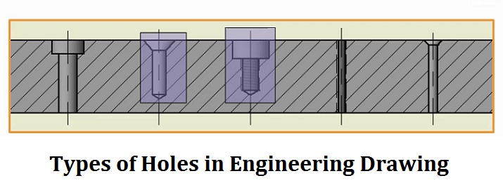
Types of Holes in Engineering Drawing
In engineering, hoes are circular features that have been cut into a material and are designed for various functions in mechanical design and manufacturing.
1. Blind Hole
A blind hole is a machined feature that penetrates partially into a workpiece without extending completely through it, typically created through drilling, boring, or milling operations. It serves as a fundamental element in mechanical design, characterized by having a bottom surface and a specified depth.
Depth:
The depth of a blind hole is usually measured from the surface to the bottom of the hole, it can include additional specifications like spot-face depth or counterbore depth. Must be precisely specified on technical drawings.
Callout Symbol:
There is not a specific symbol for blind holes, they are indicated with a diameter and a depth specification or the remaining amount of the workpiece. The standard format is Ø[diameter] ↧[depth]. For example, a callout might look like “Ø10 ↧200,” which indicates a 10 mm diameter hole with a depth of 200 mm.
Applications:
- Threaded fastener locations where through-holes are undesirable.
- Mounting points for components requiring precise depth control.
- Oil reservoirs in mechanical components.
- Locating pins and dowels in assembly fixtures.
- Weight reduction in aerospace components.
- Cable management systems in electronic enclosures.
- Fluid passages in hydraulic manifolds.
- Component alignment features in precision machinery
- Structural reinforcement points in composite materials.
2. Through Hole
A through hole is a fundamental engineering feature that creates a complete penetration through a material or component, forming an opening that extends from one surface to another. It is characterized by its full penetration nature, it is accessible and visible from both sides of the workpiece, unlike blind holes which only partially penetrate the material.
Depth:
The depth of a through hole is equal to the total thickness of the material or component it penetrates. Since it extends completely through the workpiece, the depth specification is typically not explicitly stated in technical drawings, as it is understood that the hole penetrates the entire thickness.
Callout Symbol:
The diameter symbol (Ø) is the callout symbol used for a through hole. The term “THRU” or “Through” indicates complete penetration, for example, “Ø10 THRU” represents a 10mm diameter through hole. Sometimes the thickness of the material may be included for reference.
Applications:
Mechanical fastening, mounting components using bolts, screws, or rivets.
Component alignment and positioning during assembly processes.
Creating pathways for fluid or gas flow in systems.
Weight reduction in structural components while maintaining integrity.
Electrical connections in printed circuit boards (PCBs).
Cable and wire routing in mechanical assemblies.
Ventilation and cooling purposes in equipment housings.
3. Counterbored Hole
A counterbored hole is a compound hole design featuring a wider upper hole above a smaller lower hole. It is created through a two-step drilling process where a simple hole is drilled first, followed by the creation of a wider counterbore hole above it. The design specifically accommodates bolts and enables them to sit properly in the material.
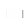
Callout Symbol
Applications:
- Providing a recessed area for fasteners to prevent snagging on surfaces.
- Accommodating washers, gaskets, or seals in mechanical assemblies.
- Ensuring a flush finish in automotive and other engineering components.
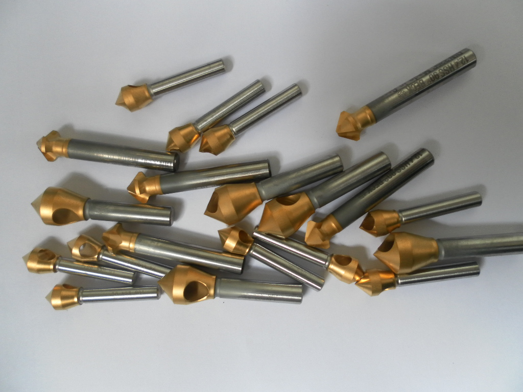
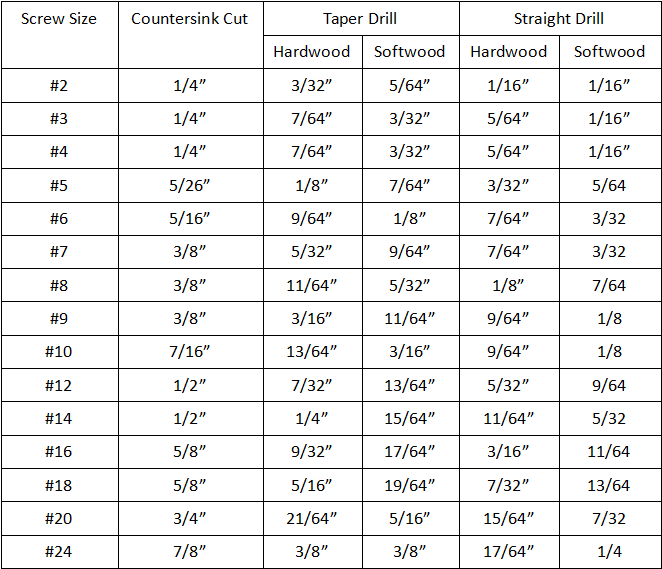
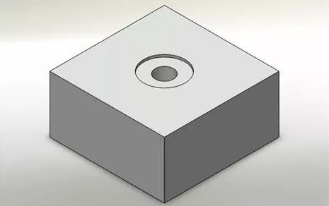
4. Countersink Hole
A countersink hole is a specialized type of hole that combines a cylindrical hole with a conical opening at the top, characterized by its distinctive V-shaped profile. This design creates a recessed area that allows screws or bolts to sit flush with or below the surface, with a specific diameter to accommodate the fastener head.
Callout Symbol
The symbol for a countersink hole is described as “V-like” in shape, which is used in technical drawings and engineering documentation to indicate the presence of a countersink feature.

Applications:
- Used in scenarios where countersunk bolts or screws are required.
- Allows for proper seating of screws, with the screw head fitting into the conical portion.
- Enables flush mounting of fasteners with the material surface.
- Particularly useful when a smooth, flat surface finish is needed after assembly.
5. Taper Hole
A taper hole is a specialized engineering feature characterized by a uniform reduction in diameter from start to end, creating a conical shape where the entrance diameter differs from the exit diameter. This gradual diameter change follows a consistent ratio, a taper hole is needed for precise fitting and secure connections.
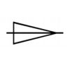
Callout Symbol:
The taper hole is indicated by a distinct symbol consisting of a triangle with a line through it. This symbol is accompanied by specifications that typically include the taper ratio (such as 1:5) to indicate the rate of diameter reduction.
Applications:
Taper holes are utilized in scenarios where secure fitting and precise component alignment are crucial.
- Accommodating specific components.
- Facilitating fastener and tool insertion.
- Creating secure tool-holding mechanisms.
- Enabling self-locking connections.
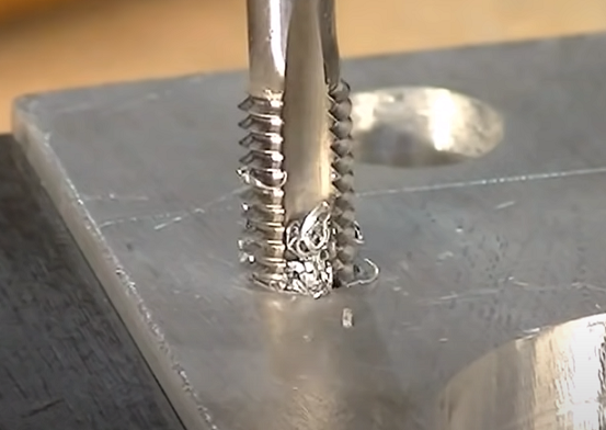
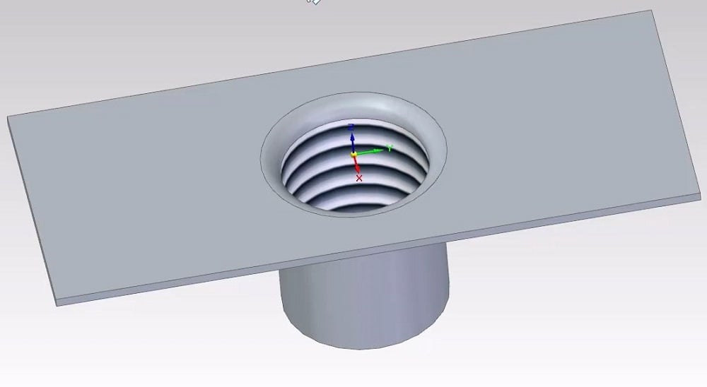
6. Tapped Hole
A tapped hole refers to a hole that has been drilled and then fitted with internal threads, typically indicated by the letter “M” in technical drawings. It’s a fundamental feature that allows for secure fastening of components using machine screws or bolts, where the internal threading matches the external threading of the fastener.
Example: M10×1 (M X by Y)
- M indicates it’s a metric thread
- 10 represents the nominal diameter
- 1 indicates the thread pitch

Applications:
Tapped holes are commonly used in various engineering applications to hold threaded components securely, such as screws, bolts, and threaded rods. They are particularly useful in metalworking where traditional fastening methods may not be feasible.
How to Read Hole Dimensions?
1. Identify the Hole Type: Determine what type of hole is being referenced, such as blind holes, through holes, or others.
2. Locate the Diameter Symbol: Look for the diameter symbol (Ø) which indicates the size of the hole. For example, a notation like “Ø10” means the hole has a diameter of 10 mm.
3. Check for Depth Information: Some holes will have a depth specified. This is often indicated with the word “Through” for holes that go all the way through the material or a specific depth measurement for blind holes. For instance, “Ø10 x 20” indicates a 10 mm diameter hole that is 20 mm deep.
4. Understand Additional Features: If the hole has additional features such as counterbores or countersinks, look for their specific symbols. The counterbore is represented by a symbol (⌴) and will include both the diameter of the counterbore and the diameter of the pilot hole. The countersink is represented by a symbol (⌵) and will include the angle and diameter of the countersink.
5. Review Tolerances: Check if there are any tolerances specified, which indicate the allowable variation in the hole dimensions.
For example, Ø20 Through means the hole has a diameter of 20 mm. It is a through hole, meaning it goes completely through the material. If the drawing specifies “Counterbore Ø20 x Ø30 x 10”, it indicates a counterbore hole where the pilot hole has a diameter of 20 mm, the counterbore has a larger diameter of 30 mm, and the depth of the counterbore is 10 mm.
Hole Machining Operations & Processes – How to Make Holes in Machining
The complete hole manufacturing process involves multiple operations.
1. Punching: A preparatory operation that creates precise positioning marks or initial depressions before drilling, helping prevent drill bit slippage and reducing vibration during the drilling process.
2. Drilling: The basic process of creating holes in solid material using a drill bit, typically used for holes where high precision isn’t required and serves as the initial operation for more refined hole-making processes.
3. Reaming: A hole finishing method that requires proper cooling with cutting fluid to improve the accuracy and surface quality of pre-drilled holes, preventing mechanical issues and ensuring proper chip removal.
4. Buried holes: A machining technique that combines drilling and end milling to create recessed holes, specifically designed to accommodate bolt heads below the surface without affecting the part’s external appearance or structural integrity.
5. Boring: A precision enlargement process for pre-formed holes using a cutting tool, which can be performed on either a boring machine or lathe to achieve more accurate hole dimensions.
6. Honing: A high-precision hole finishing method using a honing head with oil stones, involving both rotational and linear reciprocating motions, commonly used in engine cylinder bores and hydraulic components where precise diameter control is crucial.
Related Articles:
 Counterbore vs. Countersink in CNC Drilling: Differences in Symbol, Shape, Size, Tool, Application
 Countersink Size Chart (Hole & Drill Bit) | What Is a Countersink Drill Bit & & How to Use
 Spotface Hole Definition, Symbol, Dimensions & Machining – Spotface vs Counterbore
 What is A Blind Hole – How to Get Perfect Blind Hole Threads
 Tapped Holes vs. Threaded Holes: Process, Cost, Size, Material, Speed, Application, Pros & Cons
 Types of Rivets and Their Uses – Rivets Definition, Types and Applications | CNCLATHING