
Welding is a fabrication technique that joins materials and creates strong, permanent bonds. However, the complexity of welding leads to the potential for defects and imperfections that can compromise the quality and safety of welded joints. This guide introduces the most common types of welding defects with definitions, diagrams, detection methods, causes, preventive measures, and effective remedies.
What Are Weld Defects?
Weld defects, which are irregularities that occur during the welding process, can stem from inappropriate techniques, unsuitable materials, poor workmanship, and a lack of proper training or experience. These defects can manifest both on the surface of the weld bead and within the weld metal itself.
How to Check and Detect Welding Defects?
Welding defects can be identified using various inspection methods, which can be broadly categorized into non-destructive testing (NDT) and destructive testing.
Non-Destructive Testing (NDT) Methods
1. Visual Inspection
The simplest and most cost-effective NDT method, where a trained inspector examines the weld visually for surface defects such as cracks, porosity, and misalignment.
- Advantages: Quick, inexpensive, and requires minimal equipment.
- Limitations: Only detects surface defects and relies heavily on the inspector’s experience and eyesight.
- Applications: Initial screening of welds before more detailed inspection.
2. Radiographic Testing
Uses X-rays or gamma rays to create an image of the welded joint, revealing internal defects such as cracks, porosity, and incomplete fusion.
- Advantages: Highly effective for detecting internal defects, provides a permanent record of the inspection.
- Limitations: Requires specialized equipment and trained personnel, exposure to radiation hazards, and can be time-consuming.
- Applications: Critical welds in pressure vessels, pipelines, and structural components.
3. Ultrasonic Testing
Employs high-frequency sound waves to detect flaws within the welded joint. Sound waves are directed into the material, and reflections from defects are analyzed.
- Advantages: Non-invasive, highly accurate, suitable for testing thick materials.
- Limitations: Requires skilled operators, may have difficulty detecting small or thin defects.
- Applications: Pipeline welds, thick-section welds, and critical structural components.
4. Magnetic Particle Inspection
Identifies surface and near-surface defects in ferromagnetic materials by magnetizing the weld and applying fine magnetic particles that gather at defect sites.
- Advantages: Quick, cost-effective, and provides clear visual indications of defects.
- Limitations: Only works on ferromagnetic materials, may miss very fine defects.
- Applications: Surface inspection of steel structures, pipelines, and machinery components.
5. Liquid Penetrant Testing
Detects surface-breaking defects by applying a liquid dye that seeps into cracks or voids. After removing excess dye, a developer is applied to highlight the defect.
- Advantages: Simple to perform, effective on non-porous materials.
- Limitations: Only detects surface-breaking defects; may miss very fine cracks.
- Applications: Surface inspection of non-ferrous materials, aerospace components, and automotive parts.
6. Eddy Current Testing
Uses electromagnetic induction to detect surface and near-surface defects. Changes in the eddy current field caused by defects are measured.
- Advantages: Fast, can inspect complex geometries.
- Limitations: Requires conductive materials, may have difficulty with surface conditions.
- Applications: Tubing, piping, and surface inspection of conductive materials.
7. Remote Visual Inspection (RVI)
Extends visual inspection capabilities by using cameras and robotic systems to access hard-to-reach areas.
- Advantages: Allows inspection of confined spaces, reduces risk to inspectors.
- Limitations: Equipment costs and requires specialized training.
- Applications: Large-diameter pipelines, confined spaces, and hazardous environments.
8. Phased Array Ultrasonic Testing (PAUT)
A advanced form of UT that uses multiple sensor arrays to generate and receive ultrasonic waves from different angles, providing detailed cross-sectional images of the weld.
- Advantages: High resolution, multi-angle contact, rapid detection.
- Limitations: Requires specialized equipment and training.
- Applications: Critical welds in rail vehicles, pressure vessels, and complex geometries.
Destructive Testing Methods
1. Tensile Testing
A sample of the welded joint is subjected to tensile force until it fails, measuring its strength and ductility.
- Advantages: It provides quantitative data on material properties.
- Limitations: Destroys the sample and is not suitable for finished products.
- Applications: Material qualification, process validation.
2. Bend Testing
The welded joint is bent to a specified radius to evaluate its ductility and the quality of the fusion zone.
- Advantages: Simple to perform, provides information on weld metal toughness.
- Limitations: Destroys the sample, may not reveal all types of defects.
- Applications: Weld procedure qualification, material testing.
3. Charpy Impact Testing
Measures the energy absorbed by a notched specimen when struck by a pendulum, assessing the material’s toughness.
- Advantages: Provides data on material behavior under impact loads.
- Limitations: Sample preparation is required, not suitable for field use.
- Applications: Material selection, assessing weld metal properties.
4. Macroetch Testing
The welded joint is etched with acid to reveal the macrostructure, allowing visual inspection of defects such as porosity and incomplete fusion.
- Advantages: Reveals internal structure details.
- Limitations: Destroys the sample, requires careful interpretation.
- Applications: Weld procedure development, material analysis.
5. Fracture Testing
The welded joint is fractured and examined under a microscope to identify fracture mechanisms and defects.
- Advantages: Provides detailed information on fracture behavior.
- Limitations: Requires specialized equipment and sample preparation.
- Applications: Failure analysis, material research.
Different Types of Weld Defects with Images – Welding Defects Causes and Remedies
Understanding these welding defects and imperfections, their causes, and the remedies is essential for ensuring high-quality welds.
1. Undercut
The undercut welding defect is characterized by a groove or recess that forms at the toe of the weld bead, which remains unfilled. This defect typically occurs at the edges of welded joints, particularly at the corners of fillet welds, where the weld metal is not deposited adequately, creating a weakened area that can compromise the structural integrity of the weld. Refer to industry standards such as AWS D1.1, which specifies that undercuts deeper than 1/16″ (1.6mm) are typically unacceptable.

Causes
- Arc voltage is too high
- Wrong electrode or wrong electrode angle
- Large electrode
- High electrode speed
- Excessive welding current
- Improper welding technique
- Long arc length
Preventions
- Avoid excessive current; match to electrode and material
- Keep the arc length within the recommended range
- Use correct electrode angle (30°to 45°)
- Avoid excessive welding speed
- Choose appropriate filler metal
- Use properly sized consumables
- Select the right shielding gas
- Clean the workpiece thoroughly
- Weld in flat position when possible
- Control heat input via parameters
Remedies
- Grind out undercut; prepare base material
- Reweld using proper technique
- Inspect weld post-remediation
- Train welders to recognize and prevent defects
- Implement quality control procedures
2. Misalignment
Misalignment is a welding defect characterized by an improper alignment of the welded joint at the root, which can lead to weakened structures and compromised integrity. This defect manifests when two plates being welded do not align correctly, resulting in either linear or angular misalignment. Linear misalignment occurs when the plates are not parallel, while angular misalignment arises from different angular deformations between the plates. It is hard to repair the misalignment inside of pipes, so it is important to prevent the defect.
Causes
- Use of dissimilar plate thicknesses
- Carelessness during the welding process
- Lack of welder skills
- Poor component fit-up before welding
- Deformations during welding
- Breaking of tacks during welding
- Incorrect tolerance of the welding components
Preventions
- Ensure proper fit-up of workpieces before welding
- Use appropriate fixturing or clamping devices
- Train welders on proper welding techniques
- Maintain consistent travel speed, electrode angle, and arc length
- Perform visual inspections before, during, and after welding
- Use slower and more stable welding procedures
- Secure metals firmly before and during operation
Remedies
- Grind the defect portion of the joint and prepare the required shape again
- For better appearance, grind and re-weld the misaligned surface
3. Overlap
An overlap welding defect occurs when the weld face extends beyond the toe of the weld, resulting in excess material that creates an irregular weld contour. This defect is primarily a weld bead geometry issue, where the excess material protrudes from the intended weld toe, leading to a non-uniform appearance and potential structural weaknesses. Overlapping can compromise the integrity of the welded structure during its service life.

Causes
- Inadequate skills or improper methods
- Incorrect settings like voltage, current, or travel speed
- Slower travel speed causing excess material accumulation
Preventions
- Training welders in correct techniques
- Setting appropriate welding parameters
- Maintaining optimal travel speed
Remedies
- Removing excess material through grinding
- Re-welding after correcting underlying issues
- Implementing regular quality inspections
4. Burn Through
Burn-through is an undesirable defect characterized by an open hole that completely penetrates the base metal during the welding process. This defect occurs when excessive heat or welding current causes the weld material to become overly fluid, resulting in a hole that can extend through the entire thickness of the welded plate. Burn-through holes may be visible to the naked eye or may remain hidden within the welding joint, it is essential to detect the structural integrity of the weld. Non-destructive testing methods can be employed to identify these hidden defects.

Causes
- High current levels create forceful arc
- Increased heat input causing excessive fluidity
- Inadequate heat distribution control
- Extreme gap to the root
- Insufficient metal on the root surface
Preventions
- Lowering overall heat input
- Increasing welding travel speed
- Employing heat sinks like copper backing
Remedies
- Repairing or re-welding affected areas
- Regular non-destructive testing inspections
- Revising welding parameters
5. Incomplete Fusion (Lack of Fusion)
Incomplete fusion is a welding defect characterized by the failure of the weld metal to form a cohesive bond with the parent metal, resulting in gaps or voids between these two materials. This defect can manifest in various forms, such as a lack of side wall fusion, where the weld does not adequately bond with the sides of the joint, or a lack of root fusion, where the weld fails to connect at the root of the joint. Additionally, inter-run fusion issues occur when there is insufficient bonding between successive weld passes, leading to weak joints that can compromise the structural integrity of the weld.

Causes
- Insufficient current causing inadequate heat
- Fast travel speed preventing proper fusion
- Short arc leading to poor heat transfer
- Contaminants inhibiting proper bonding
- Lack of preheat causing thermal shock
Preventions
- Set welding parameters according to specifications
- Thoroughly clean surfaces before welding
- Preheat base material as needed
- Maintain proper technique and travel speed
- Perform regular quality checks
Remedies
- Grind out and reweld affected areas
- After repair, conduct tests to verify the integrity of the weld
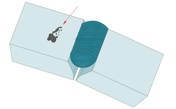
6. Slag Inclusion
There are two types of inclusion defects on welded parts: slag and tungsten. The slag inclusion is characterized by the entrapment of slag within the weld metal, which can compromise the integrity and strength of the weld. This defect typically occurs in welding processes that utilize slag as a protective medium, such as submerged arc welding (SAW) and shielded metal arc welding (SMAW). Slag, which forms as a byproduct of the welding process, can become trapped between layers of weld metal or within the weld itself, especially during multi-layer or multi-pass welding. Slag inclusions may lead to reduced mechanical properties, increased porosity, and potential failure of the weld.

Causes
- Low current causing inadequate melting
- Multi-pass welding traps slag between layers
- Residual contaminants on surface
- Damaged electrode coatings
- Inadequate cleaning between passes
Preventions
- Increase current within recommended range
- Preheat base material to reduce thermal gradient
- Thoroughly clean the surface before welding
- Use electrodes with intact coatings
- Clean between passes
Remedies
- Remove the defect by grinding operation and re-weld
7. Spatter
A spatter welding defect refers to small particles of weld metal that are expelled during the welding process and adhere to the surface of the parent metal. This phenomenon typically occurs when the arc length is too high, causing the metal droplets to become globular. When these droplets fall into the weld pool, there is a risk of molten metal being pushed outside the intended weld area, resulting in spatter. This defect can compromise the appearance and integrity of the weld, leading to additional issues if not addressed.
Causes
- Extended arc length increasing droplet expulsion
- Globular droplets detaching from electrode
- Incorrect voltage, current, or travel speed
- Insufficient shielding gas flow
Preventions
- Optimize voltage, current, and travel speed
- Apply high-temperature protective coatings
- Maintain appropriate arc length
- Ensure adequate shielding gas flow
Remedies
- Grind or sand affected areas
- Use solid blasting techniques
- Clean surface thoroughly post-welding
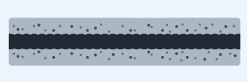
8. Porosity
Porosity is a welding defect characterized by the presence of small gas bubbles or voids within the weld metal. These tiny imperfections can compromise the integrity and strength of a weld, leading to potential failures under stress. Porosity typically occurs when the welding process is disrupted, allowing gases to become trapped during solidification. This can manifest in various welding techniques, including gas metal arc welding and flux-cored arc welding, where inadequate shielding or contamination of the base material contributes to the defect.

Causes
- Too fast travel speed
- High wind speeds during outdoor welding
- Impurities or residues in the base metal
- Extremely short arc length
- Wrong electrode
- Presence of moisture in the electrode
- Insufficient cubic feet per hour of shielding gas
Preventions
- Avoid high wind conditions or use windbreaks during outdoor welding
- Ensure correct shielding gas flow rate for the welding process
- Thoroughly clean base materials before welding to remove contaminants
- Follow recommended practices for torch angle, speed, and heat input
- Pay attention to humidity and temperature during welding
Remedies
- Grind out porosity and re-weld affected sections
- Implement more rigorous cleaning methods for base materials
- Modify gas flow rates and welding speeds to prevent porosity
- Use non-destructive testing methods to identify and assess porosity
9. Cracks
Crack welding defects are planar discontinuities characterized by a significant length-to-opening displacement ratio. These cracks can occur in the weld metal, the heat-affected zone (HAZ), or the base material and may manifest in various orientations. They are typically formed due to thermal stresses during the welding process, either at elevated or low temperatures. Cracks are considered one of the most detrimental weld discontinuities because they act as severe stress concentrators, leading to potential failure. The presence of cracks indicates a loss of metallurgical control, making them unacceptable according to most fabrication codes, regardless of their size. There are many different types of crack defects in welding, including root crack, crater crack, fusion zone crack, fusion line crack in HAZ, underbead crack in HAZ, transverse crack in HAZ, longitudinal crack in weld, and transverse crack across weld.
Causes
- Temperature gradients creating thermal stresses
- Weld bead contraction causing stress concentrations
- Chemical composition differences leading to embrittlement
- Grain boundary weakening
- Improper contraction during cooling
Preventions
- Use controlled cooling rates
- Choose compatible materials
- Minimize temperature gradients via techniques
- Preheat base material
- Apply post-weld heat treatment
Remedies
- Remove by gouging or grinding
- Rework affected area
- Replace cracked components
10. Arc Strike
Arc strike defects occur when an electric arc unintentionally contacts the base metal outside of the intended weld zone, often as a result of carelessness or lack of attention during the welding process. This can happen when the welder inadvertently scratches the workpiece with a live electrode, leading to discontinuities in the metal. Arc strikes can create micro-cracks not only in the weld area but also in the surrounding base metal, especially in structures subject to cyclic loading. These cracks can propagate over time, compromising the integrity of the weld and the overall structure. The presence of arc strikes poses a significant risk, as inspectors may require costly repairs or removals of affected sections.
Causes
- Welders distracted or inattentive
- Moving stuck electrode back and forth
- Inexperienced welders handling equipment unsafely
- Faulty or poorly maintained equipment
Preventions
- Proper techniques and safety procedures
- Concentrate on work, avoid distractions
- Safely handle stuck electrodes
- Keep equipment in good condition
Remedies
- Identify and assess arc strikes
- Grind out defect, repair weld, or replace section
11. Insufficient Fill
An insufficient fill welding defect, also known as underfill or under filled, is a type of welding defect where the weld surface is below the adjacent surface of the workpiece material. This can occur on either the front or back side of the weld. When it occurs on the back side, it is also known as suck back welding defect or under fill welding defect.

Causes
- Low welding current
- Too high travel speeds
- Incorrect weld bead placement
- Laying weld beads too thinly in multi-pass welds
Preventions
- Proper electrode size selection
- Selecting the right current setting
- Avoid moving too fast
- Ensure proper joint preparation
- Use appropriate welding techniques
Remedies
- Grind to remove the defect, and then reweld with the correct amount of filler metal
- During repair, ensure the welding technique is appropriate
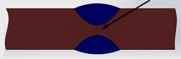
12. Insufficient (Incomplete) Penetration
Lack of penetration, also known as incomplete penetration, is a welding defect characterized by insufficient fusion between the base metal and the weld metal, resulting in a gap at the root of the weld joint. This defect typically occurs in groove welds when the weld metal does not fully penetrate the joint, leading to reduced strength and potential failure under load. To identify lack of penetration, visual inspection may reveal an incomplete fill at the joint, while more detailed assessments can be conducted using non-destructive testing methods such as ultrasonic testing or radiographic inspection, which can detect the presence and extent of the voids within the weld.
Causes
- Inadequate welding parameters (low current, high travel speed)
- Poor joint preparation (incorrect geometry, alignment, or root gap)
- Incorrect electrode selection (wrong size or type)
- Improper welding technique (incorrect angle or manipulation)
- Contamination in the joint area
Preventions
- Use appropriate welding parameters (current, voltage, travel speed)
- Proper joint preparation (geometry, alignment, root gap)
- Select suitable electrodes for the joint and material
- Maintain proper welding technique
- Clean the joint area thoroughly before welding
Remedies
- Rework the weld by grinding out the defective area and rewelding
- Modify joint design if necessary
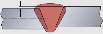
13. Excessive Reinforcement
Excessive reinforcement in welding is a defect characterized by an overabundance of weld metal beyond the specified size or profile, leading to dimensional inaccuracies and potential stress concentration points in the welded joint that can compromise structural integrity and performance. This defect typically manifests as protrusions, uneven or overly pronounced weld beads that extend beyond acceptable dimensions, creating surface irregularities such as bumps or ridges. The excessive weld metal deposition not only affects the appearance but also creates areas of stress concentration that may lead to fatigue and failure under operational loads.

Causes
- Low travel speeds during welding
- Incorrect procedures or techniques
- Excessive flux on the feed wire
- Wrong joint fit-up
- Too much current
- Insufficient or uneven flux application
Preventions
- Maintain optimal torch speed
- Use proper welding techniques
- Monitor and control welding parameters
- Align workpieces properly
- Select appropriate joint fit-up
- Set correct amperage and voltage
Remedies
- Grind down excessive filler metal
- Reweld the affected area
- Implement quality control checks
- Adjust techniques based on inspection feedback
Related Articles:
 What is Heliarc Welding – Principle, Machine, Use, Cost, Difference Between TIG and Heliarc Welding?
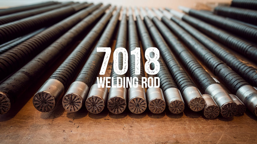 7018 Welding Rod Specifications: Properties, Amperage (Sizes) Chart, Uses, 7014 vs 7018 Electrodes
 What is Welding Process and How Does It Work – Types of Welding and Their Uses
 How to Weld Aluminum – Is Aluminum Hard to Weld & What Aluminum is Unweldable?
 Types of Welding Used for Sheet Metal – How to Weld Sheet Metal for Beginners
 Different Welding Types and Applications Comparison