Screws and bolts are used in all kinds of machinery, buildings, and structures. When joining parts with threaded portions, or when fixing a part to another part using bolts, torque is applied to rotate and tighten the parts or bolts. At this time, the force in the axial direction that prevents the separation of the parts and parts is called the “axial force”. In this way, to prevent loosening of the screws, it is important to properly manage the axial force when tightening the screws. The axial force pushes the parts together in the axial direction to prevent them from separating. Proper management of the axial force is important for preventing loosening of the screws. In this article, we will explain to those of you with concerns about axial force on fastener and the mechanisms behind it. We hope this axial force guide helps with optimizing product selection at the design stage, as well as hints for improving the efficiency of daily inspections and maintenance work.

Screws are an important component used in all kinds of manufacturing sites and their products, not just vehicles, railways, and aircraft, but also buildings like houses and bridges, and even the smartphones in your hands. A single trouble with a screw or bolt can even trigger a serious accident. Screw loosening refers to “a state where the axial force has decreased from when it was tightened.”
Related Read: What is Radial Force – Radial Force Definition, Formula (Equation), Test, Radial vs Axial Force
What is Axial Force?
Axial force refers to the “tensile force” generated as the stretched bolt reacts and tries to return to its original position when tightened.
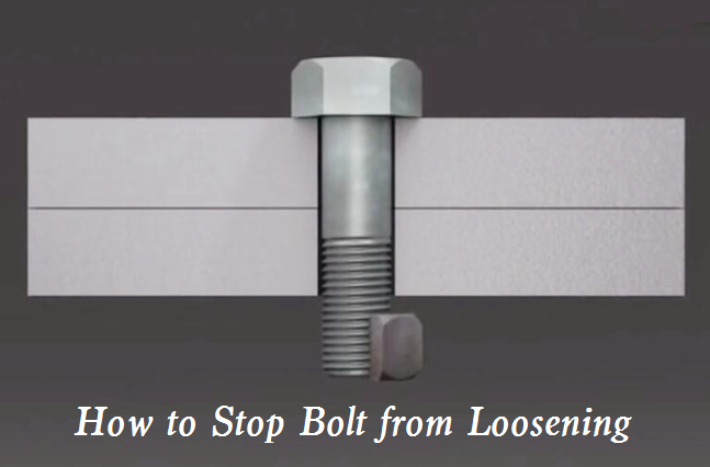
As bolts and nuts are tightened as shown in Figure 1, the parts being joined are compressed and compressed force is generated, and the bolt is pulled and tensile force acts on it. This tensile force is called the axial force. The bolt and nut prevent the force that loosens the threads by the axial force acting to generate friction between the seated surfaces and threaded surfaces. On the other hand, if the axial force decreases and the friction between the seated and threaded surfaces becomes small, the force that loosens the threads prevails and thread loosening occurs.
In the case of high precision bolt tightening, it is difficult to maintain a constant axial force on the bolt solely through torque control, as it is affected by variations in the friction coefficients of the bolts and seated surfaces. As a result, even with the same torque value, there will be variations in the axial force of the bolts.
However, with an axial force control method that uses a bolt tensioner or hydraulic nut to apply a tensile load to the bolt during tightening, the influence of friction can be eliminated and the axial force of the bolt can be controlled directly. In addition, no torsional stresses are generated.
Axial Force Diagram
An axial force diagram is a type of free body diagram that illustrates the internal axial forces (tensions and compressions) acting within a structural element like a beam, truss member, shaft etc.
Some key points about axial force diagrams:
- They are drawn after analyzing the external loads and reactions on a structural element using a free body diagram.
- The structural element is divided into sections at points where forces change magnitude.
- Axial forces are drawn as arrows along the axis of each section, indicating if it is in tension (pulling) or compression (pushing).
- The directions of arrows must be consistent with the direction of external forces as per the basic mechanics principles.
- The magnitude of forces is usually proportional to the length of arrows.
- Forces balance at the boundaries between sections as per the law of actions and reactions.
- They help visualize and calculate the internal stresses developed within the member due to external loads.
- Engineers use axial force diagrams to design structures, check their strength and stability against failure.
Here are the main steps to draw an axial force diagram:
- Draw the free body diagram of the object or structure you are analyzing. Include all relevant external forces acting on it like loads, reactions, etc.
- Break the body into sections at points where internal forces change, like points of application of loads or reactions.
- Write the internal axial forces (tension or compression) acting on each section. The forces act collinearly along the longitudinal axis of each section.
- Draw the forces as arrows acting at the boundary of each section. The direction of the arrow indicates whether it’s a tensile (pulling) or compressive (pushing) force.
- Ensure the arrow directions are consistent with the external forces. For example, if a load is pushing down, the internal force right below it will be in compression.
- The sum of all axial forces at a section boundary must be zero based on the law of actions and reactions.
- Label all forces clearly. Common notations used are T for tension and C for compression.
- Dimension the arrows proportionately relative to the magnitude of forces.
- Add notes as needed to explicitly state assumptions and direction of positive forces.
Referring to these steps should help you systematically construct an accurate axial force diagram for the structural element you want to analyze.
Tightening Torque vs Axial Force
On the other hand, in the assembly manufacturing process, tightening torque management and tightening angle management are methods for managing whether parts or bolts are correctly assembled. Tightening by angle control is called ‘angle tightening’. So what is torque? In mechanics, torque is the moment of force around a fixed rotational axis. However, in screw fastening, consider the case where a hexagonal nut is used to secure a hexagonal bolt passed through the object to be fastened. Tighten with a wrench using the center of the bolt as the rotation axis, but you will have to turn the wrench around and around. The moment of force generated during this rotation is torque. In other words, tightening torque is the torque (force in the rotational direction) that is applied to the head of a nut or bolt during tightening. If the axial force is not within the appropriate range, it may cause loosening or damage the fastened parts, so it is important to manage the tightening torque and axial force appropriately on a daily basis.
Now, how do we find the necessary tightening torque to manage the appropriate axial force? You can find it using the simple calculation formula below.
Axial Force Setting and Friction
In joint design, it must be designed to withstand external forces that try to separate. In bolt tightening, the tightening state is maintained by axial force F2 against axial external force F1 that loosens the bolt. With F2> F1, loosening is eliminated, but as an axial force setting, a safety factor α is set and F3 = αxF2.
In calculation, the tightening torque T3 and tightening axial force F3 become a simple conversion, but in actual tightening and loosening, what is important is the friction of the bolt portion and seat surface. If the friction of the bolt portion and seat surface is greater than expected during tightening rotation, a torque higher than the setting is required, and if the friction of the bolt portion and seat surface is lower than expected during loosening rotation, it will loosen with a torque lower than the setting. In other words, even with the same tightening torque, different axial forces mean it can loosen under a load lower than expected even when tightened with the specified torque.
Axial Force Control: Tightening Torque Control and Tightening Angle Control
Since the resistance to separation is ultimately axial force, what is important in quality control in assembly manufacturing is guaranteeing the axial force. Tightening torque control can be applied if friction can be stably managed with low variability influence, and there is sufficient correlation with axial force.
There are two methods for axial force control. One is by measuring axial force, and the other is angle tightening.
In angle tightening, the tightening angle is used as a reference value in the tightening process. The tightening torques at multiple angle (rotation) positions are also confirmed to be within a certain range (window) simultaneously. If the correlation between tightening angle and torque can be managed within the assumed range, it means friction is also being properly controlled. This in turn means axial force is being properly controlled.
In angle tightening, ‘plastic zone angle tightening’ allows reducing axial force variability and obtaining larger axial force. This method initially tightens the bolt up to the yield point of the thread, then tightens to the specified angle. However, plastic deformation is involved, so the same bolt cannot be reused in the same manner.
Axial Force Formula & Equation
The axial force (tensile force) generated in the bolt during tightening must be 70% or less of the yield stress of the bolt material. It is necessary to ensure that the proper axial force generated in the bolt by tightening never exceeds the allowable value, which is the yield stress. Suppose you tighten a bolt with a wrench that is too large for the size of the bolt. If the axial force generated by tightening the bolt exceeds the allowable value, the threaded part will be scraped, or the bolt will become threaded and break. Therefore we need to calculate the appropriate axial force!
Calculation sheet to determine how much axial force will occur when tightening a bolt with a certain torque.
Simple Axial Force Formula & Equation is as follows:
- Axial force: F=T/(k・d)
- Torque: T=kFd
- F: Axial force applied to the bolt [N]
- T: Torque applied to the bolt [N・m]
- k: Torque coefficient (e.g. 0.2)
- d: Bolt diameter (nominal diameter) [m]
Derivation of a simple calculation formula
To perform safe bolt tightening, sufficient initial preload force Ff is necessary, and appropriate tightening torque T must be applied. Therefore, it is important to understand the relationship between the axial force Ff and tightening torque T, as well as the various factors that affect this relationship.
Based on this, we will start by understanding the principle of torque T. Torque refers to the “twisting moment” that acts around the rotational axis as the center of rotation, and the amount is obtained by multiplying the force and the distance from the rotational axis to the center. In other words, when tightening work is performed using a torque wrench or other tightening tool, the torque is the product of the applied force and the distance from the center of rotation. The bolt is pulled in the axial direction by the horizontal rotational force/torque, generating axial force.
Axial Force Calculation – How To Calculate Axial Force?
We think you now fully understand the simple axial force formula, so now let’s calculate some axial forces.
There are two axial forces we will calculate:
- Initial preload axial force (hereinafter referred to as preload axial force) – It is the magnitude of the axial force generated when tightening the bolt with a certain tightening torque.
- Yield preload axial force – It is the magnitude of the axial force on the bolt that causes the stress (please search) generated when tightening the bolt to exceed the yield point (please search) of the bolt material.
For both frictional joints and tensile joints, a stronger joint can be achieved with a larger axial force as long as the bolt seating does not sink in. Therefore, we usually try to set the tightening torque to apply an axial force as close to 2) the yield preload axial force as possible without exceeding it.
How To Calculate Initial Preload Axial Force?
There are complicated and simple calculation formulas, but we will use a practical simple calculation formula.
Let F(N) be the axial force generated by the bolt, T(Nm) be the tightening torque, and d(m) be the bolt nominal diameter. Then:
T = F × d × K (Nm)
Now we want to determine the axial force F from the tightening torque, so:
F = T/d/K
Here, K is the torque coefficient which is determined by the friction coefficient of the threaded part and seating surface and the effective friction radius of the seating surface. The friction coefficient also varies depending on the lubrication condition. In practice, the axial force is actually measured to determine the torque coefficient value, but for now we will calculate using the following general values:
Values of the torque coefficient K for each lubrication condition:
- No lubrication: 0.3~0.4
- Oil: 0.15~0.25
- Wax: 0.1~0.2
These are just general values, so actual measurement is necessary.
How To Calculate Yield Tightening Axial Force?
The yield tightening axial force Fy is calculated using the following formula:
Let the yield tightening axial force be Fy,
- Fy = σy・As / (1+3{3/dAS×(P/2/π+0.577×μth×d2)}^2)
Here, σy is the yield strength of the bolt material (Pa), As is the effective cross-sectional area of the threaded portion (m²), dAS is the equivalent diameter of the effective cross-sectional area of the threaded portion (m), P is the screw pitch (m), μth is the coefficient of friction of the threaded portion, and d2 is the effective diameter of the screw (m).
What this formula implies is that if the axial force exceeds this value, the entire bolt will yield.
It is important to note that even below this yield tightening axial force, the surface of the bolt has already yielded.
The calculation of the yield tightening axial force requires the coefficient of friction of the threaded portion, but this cannot be determined without knowing the lubrication condition, so we will calculate using the following general values.
Values for the coefficient of friction of the threaded portion μth
- No lubrication: 0.21 to 0.28
- Oil: 0.10 to 0.18
- Wax: 0.06 to 0.14
Furthermore, we cannot calculate without knowing the yield strength σy of the bolt material.
How To Calculate Axial Force of A Blot?
Calculating the axial force on a bolt typically involves determining the amount of preload applied to the bolt during installation and any additional forces applied when the bolted joint is subjected to external loads. Here are the steps to calculate the axial force on a bolt:
- Initial Preload: When a bolt is tightened, it’s stretched slightly, and this tension creates a clamping force that holds the joint together. This initial force is known as the preload, and it’s usually specified by the manufacturer or determined by the torque applied when tightening the bolt.
- Torque-Preload Relationship: If the preload is not directly specified, you can estimate it from the torque applied to the bolt using the following relationship:

This equation is a simplified representation and assumes that all the torque goes into stretching the bolt, which is not entirely accurate since some torque is also lost to overcome friction.
- External Loads: If the bolted assembly is subject to external forces, these forces will either add to or subtract from the preload. The total axial force on the bolt can increase to the point where it equals the yield strength of the bolt material, potentially leading to bolt failure.
- Calculate Total Axial Force: Assuming the preload has been determined and you know the external axial load applied to the joint, the total axial force on the bolt at any given time is:

- Factor in Joint Deformation: In practice, when external loads are applied to the joint, some of the load may be absorbed by the deformation of the joint components, thereby reducing the load on the bolt. This aspect is often analyzed using a joint diagram, which plots bolt force against joint compression.
- Safety and Fatigue Considerations: To ensure the bolted joint is reliable, it’s important to consider both the safety factor against static overload and the fatigue life of the bolt. The total axial force should not exceed the bolt’s yield strength divided by the desired safety factor. Additionally, cyclic loads can lead to fatigue failure even if the force is below the yield strength, so the fluctuating axial force must also be analyzed for fatigue considerations.


