
Gear couplings are essential components in many industrial applications, which sizes are available, and how to select them? This article will talk about what gear couplings are, how they work, manufactured, their dimensions, and their differences from other types of couplings. Additionally, we will provide full and half gear coupling size charts to aid in selection and application.
What Is Gear Coupling?
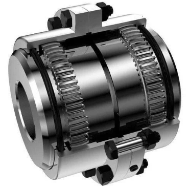
A coupling in mechanical connection refers to a machinery device that connects two shafts together. The gear coupling is one of the types of couplings, used for the transmission of torque and rotational movement between two non-aligned shafts. It consists of two flexible joints, each attached to one shaft, connected by a central spindle, enabling power transfer even under misalignment. This design enables gear couplings to accommodate angular misalignment and parallel misalignment, they are suitable for high-torque applications where flexibility and misalignment compensation are required. Unlike rigid couplings, which do not allow any movement between shafts, gear couplings provide a flexible connection that can handle significant misalignment while maintaining high torque transmission capabilities, making them distinct from other coupling types such as rigid or flexible couplings.
The manufacturing process of gear couplings involves lots of techniques. For high-strength applications, the hubs are often forged. The forging process involves heating the metal and shaping it under high pressure to create a dense, strong component. In some cases, especially for larger or more complex shapes, the hubs may be cast. This involves pouring molten metal into a mold and allowing it to solidify. In addition, the gear teeth are machined with high precision to ensure accurate meshing and efficient torque transmission. This is typically done using gear cutting machines like hobbing machines or gear shapers.
Full Gear Coupling vs Half Gear Half Rigid Coupling
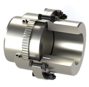
A full gear coupling consists of two toothed hubs fixed to both the driver and driven shafts, connected by sleeves with internal teeth that mesh with the hubs to enable torque transmission. This design accommodates both angular and parallel misalignment, full gear coupling is ideal for various industrial applications requiring high torque transmissions, such as in heavy machinery or hoisting mechanisms, where it connects the driving motor to the gearbox or smaller wire rope drums. In contrast, a half gear half rigid coupling features a combination of a rigid flanged hub and a flexible geared sleeve that meshes with the rigid hub. This design is ideal for applications where one shaft must remain fixed while the other accommodates slight misalignments, ensuring functionality in machinery where perfect alignment cannot be maintained but is still necessary to some extent.
How Does a Gear Coupling Work?
A gear coupling typically includes two hubs with external gear teeth and a flexible sleeve with internal gear teeth. The hubs are attached to the two shafts, while the sleeve meshes with the hubs. When the driving shaft rotates, it drives the hub attached to it. This rotation is transferred through the meshing gears to the flexible sleeve, which in turn drives the hub on the driven shaft. This mechanism ensures efficient torque transmission despite shaft misalignment. The gear teeth are designed to allow for angular and parallel misalignment between the shafts.
For example, a hoist mechanism where a gear coupling connects the driving motor to the gearbox. The motor shaft and gearbox shaft may not be perfectly aligned due to installation errors or operational conditions. The gear coupling’s flexible design allows it to compensate for this misalignment while efficiently transferring torque from the motor to the gearbox. This ensures smooth operation and reduces wear on other components.
How to Calculate the Gear Coupling Sizes?
To calculate the size of a gear coupling, you need to consider various factors related to the application and the specific requirements of the coupling.
1. Determine System Torque
If the torque is not given, you can calculate it using the following formula:
System Torque (T) [Nm] = Power [kW] × 9550 / Speed [r/min]
For example, if you have a motor with 30 kW power and a speed of 1440 r/min: System Torque = 30 × 9550 / 1440 = 203.13 Nm
2. Determine the Service Factor
The service factor is a multiplier that accounts for the operating conditions and load characteristics. It can be found in standard tables provided by coupling manufacturers. For example, a typical service factor for a motor-driven application might be 1.0.
3. Calculate the Required Coupling Rating
Multiply the system torque by the service factor to get the required coupling rating:
Required Coupling Rating = Service Factor × System Torque
For example, if the service factor is 1.0 and the system torque is 203.13 Nm, Required Coupling Rating = 1.0 × 203.13 = 203.13 Nm
4. Select the Appropriate Coupling Size
Refer to the product tables provided by the coupling manufacturer to select a coupling with a torque rating equal to or greater than the required coupling rating. Ensure that the selected coupling can accommodate the shaft diameters and other dimensional requirements.
5. Consider Additional Factors
- Speed Capacity: Ensure that the coupling’s maximum speed rating exceeds the operating speed of the system.
- Shaft Diameters: Verify that the coupling’s bore capacity can fit the shaft diameters.
- Shaft Extensions: Check that the coupling’s minimum shaft length requirements are met.
Gear Coupling vs Grid Coupling, What Are the Differences?
For high-torque, heavy-duty applications where durability and high-speed performance are critical, gear couplings may be ideal. Grid couplings are better suited for applications requiring high misalignment tolerance, vibration dampening, and moderate torque transmission.
| Feature | Gear Coupling | Grid Coupling |
|---|---|---|
| Design | Consists of two hubs with external gear teeth meshing with an internal sleeve. | Comprises two hubs connected by a flexible metallic grid. |
| Torque Capacity | High torque capacity, up to 12,500,000 Nm. | Moderate torque capacity, up to 70,000 Nm. |
| Misalignment Tolerance | Limited misalignment tolerance, suitable for low angular and axial misalignments. | High misalignment tolerance, suitable for angular and parallel misalignments. |
| Speed Capability | Suitable for high-speed applications. | Can operate at speeds up to 4500 RPM. |
| Vibration Dampening | Limited vibration dampening. | Excellent vibration dampening. |
| Shock Absorption | Limited shock absorption. | Good shock absorption due to flexible grid. |
| Maintenance | High maintenance is required, including lubrication and frequent inspection. | Moderate maintenance is required, including lubrication. |
| Cost | Higher initial and maintenance costs. | Moderate initial and maintenance costs. |
| Installation Complexity | More complex installation due to its heavy-duty nature. | Moderate installation complexity. |
| Applications | Heavy-duty applications such as mining, steel mills, and power generation. | General industrial applications, HVAC systems, conveyors, and pumps. |
Fluid Coupling vs Gear Coupling, What Are the Differences?
In summary, choosing fluid couplings for applications requiring smooth starts, overload protection, vibration dampening, and gear couplings can ensure high precision and efficiency when high torques are needed.
| Feature | Fluid Coupling | Gear Coupling |
|---|---|---|
| Working Principle | Transmits torque using hydraulic principles with no direct mechanical contact. | Transmits torque through meshing gear teeth between two hubs. |
| Torque Capacity | Lower torque capacity compared to gear couplings. | High torque capacity, suitable for heavy-duty applications. |
| Misalignment Tolerance | Moderate misalignment tolerance. | Limited misalignment tolerance, better for low angular and axial misalignments. |
| Speed Capability | Suitable for a wide range of speeds. | High-speed applications are possible. |
| Vibration Dampening | Excellent vibration dampening. | Limited vibration dampening. |
| Shock Absorption | Good shock absorption. | Limited shock absorption. |
| Maintenance | Low maintenance is required. | High maintenance is required, including lubrication. |
| Efficiency | Lower efficiency due to hydraulic losses. | High efficiency due to direct mechanical transmission. |
| Soft Start Capability | Smooth, soft starts, reduces wear on machinery. | No soft start capability. |
| Overload Protection | Provides overload protection by slipping under heavy loads. | No inherent overload protection. |
| Cost | Higher initial and maintenance costs. | Moderate initial and maintenance costs. |
| Applications | Ideal for conveyors, pumps, fans, and applications requiring soft starts. | Suitable for heavy-duty applications like mining, steel mills, and power generation. |
Gear Coupling Sizes (Dimensions)
Full Gear Coupling Size Chart (MM)
| Sizes | Max. Bore (mm) | Pilot Bore (mm) | Load Torque (kg.M) | Capacity (h.p. per 100 RPM) | Max. RPM | Wt. with Solid Hubs (kg) | GD² | Dimensions (mm) | ||||||||
| A | B | C | D | E | F | G | H | M | ||||||||
| 100 | 35 | 10 | 50 | 7 | 8000 | 4.2 | 0.03 | 120 | 75 | 50 | 39.5 | 93 | 15 | 45 | 1.5 | 45 |
| 101 | 50 | 20 | 100 | 14 | 6300 | 10 | 0.14 | 170 | 110 | 65 | 49 | 115 | 17 | 55 | 2.5 | 65 |
| 102 | 60 | 30 | 250 | 35 | 5000 | 15 | 0.2 | 185 | 125 | 85 | 62 | 145 | 17 | 70 | 2.5 | 80 |
| 103 | 75 | 40 | 450 | 63 | 4000 | 26 | 0.48 | 220 | 150 | 105 | 78 | 175 | 20 | 85 | 2.5 | 105 |
| 104 | 90 | 50 | 850 | 119 | 3350 | 40 | 0.95 | 250 | 175 | 130 | 96 | 215 | 20 | 105 | 2.5 | 125 |
| 105 | 110 | 60 | 1300 | 182 | 2800 | 62 | 1.9 | 290 | 200 | 155 | 106 | 230 | 25 | 110 | 5.0 | 140 |
| 106 | 125 | 75 | 2000 | 280 | 2500 | 85 | 3 | 320 | 230 | 175 | 117 | 260 | 25 | 125 | 5.0 | 155 |
| 107 | 140 | 90 | 3500 | 490 | 2100 | 120 | 5.25 | 350 | 260 | 205 | 134 | 290 | 25 | 140 | 5.0 | 175 |
| 108 | 160 | 105 | 4500 | 630 | 1900 | 180 | 8.5 | 380 | 290 | 230 | 147 | 320 | 25 | 155 | 5.0 | 190 |
| 109 | 180 | 125 | 5600 | 784 | 1700 | 210 | 15 | 430 | 330 | 250 | 156 | 340 | 25 | 165 | 5.0 | 205 |
| 110 | 220 | 140 | 8200 | 1148 | 1400 | 290 | 30.5 | 490 | 390 | 310 | 171 | 370 | 25 | 180 | 5.0 | 220 |
| 111 | 260 | 160 | 11000 | 1536 | 1250 | 550 | 58 | 545 | 445 | 350 | 192 | 410 | 30 | 200 | 5.0 | 240 |
| 112 | 300 | 180 | 14700 | 2053 | 1120 | 710 | 88 | 590 | 490 | 400 | 231 | 490 | 30 | 240 | 5.0 | 280 |
| 113 | 330 | 200 | 20000 | 2793 | 1000 | 980 | 138 | 680 | 555 | 440 | 242 | 535 | 35 | 260 | 7.5 | 310 |
| 114 | 370 | 220 | 28600 | 3994 | 900 | 1320 | 291 | 730 | 610 | 500 | 266 | 575 | 35 | 280 | 7.5 | 330 |
| 115 | 410 | 250 | 34750 | 4852 | 800 | 1700 | 353 | 780 | 660 | 540 | 305 | 655 | 35 | 320 | 7.5 | 370 |
| 116 | 455 | 300 | 60000 | 8378 | 710 | 2550 | 680 | 900 | 755 | 625 | 335 | 720 | 45 | 350 | 10.0 | 425 |
| 117 | 520 | 375 | 83350 | 11917 | 630 | 3620 | 1235 | 1000 | 855 | 720 | 386 | 820 | 45 | 400 | 10.0 | 460 |
| 118 | 610 | 450 | 113000 | 15778 | 560 | 4860 | 1965 | 1100 | 950 | 810 | 430 | 920 | 55 | 450 | 10.0 | 510 |
| 119 | 710 | 520 | 149000 | 20805 | 500 | 3680 | 3012 | 1250 | 1050 | 910 | 446 | 1000 | 55 | 485 | 15.0 | 560 |
Half Gear Half Rigid Coupling Size Chart (MM)
| Sizes | Max. Bore (mm) | Pilot Bore (mm) | Load Capacity | Max. RPM |
Wt. with Solid Hubs (kg) | GD² | Dimensions (mm) | ||||||||||
| A | B | C | D | E | F | G | H | M | |||||||||
| Gear | Rigid | Torque | H.P. per 100 RPM |
||||||||||||||
| 100 | 35 | 50 | 10 | 50 | 7 | 8000 | 4.2 | 0.03 | 120 | 75 | 50 | 39.5 | 93 | 15 | 45 | 1.5 | 45 |
| 101 | 50 | 60 | 20 | 100 | 14 | 6300 | 10 | 0.14 | 170 | 110 | 65 | 49 | 115 | 17 | 55 | 2.5 | 65 |
| 102 | 60 | 75 | 30 | 250 | 35 | 5000 | 15 | 0.2 | 185 | 125 | 85 | 62 | 145 | 17 | 70 | 2.5 | 80 |
| 103 | 75 | 90 | 40 | 450 | 63 | 4000 | 26 | 0.48 | 220 | 150 | 105 | 78 | 175 | 20 | 85 | 2.5 | 105 |
| 104 | 90 | 110 | 50 | 850 | 119 | 3350 | 40 | 0.95 | 250 | 175 | 130 | 96 | 215 | 20 | 105 | 2.5 | 125 |
| 105 | 110 | 130 | 60 | 1300 | 182 | 2800 | 62 | 1.9 | 290 | 200 | 155 | 106 | 230 | 25 | 110 | 5.0 | 140 |
| 106 | 125 | 150 | 75 | 2000 | 280 | 2500 | 85 | 3 | 320 | 230 | 175 | 117 | 260 | 25 | 125 | 5.0 | 155 |
| 107 | 140 | 170 | 90 | 3500 | 490 | 2100 | 120 | 5.25 | 350 | 260 | 205 | 134 | 290 | 25 | 140 | 5.0 | 175 |
| 108 | 160 | 200 | 105 | 4500 | 630 | 1900 | 180 | 8.5 | 380 | 290 | 230 | 147 | 320 | 25 | 155 | 5.0 | 190 |
| 109 | 180 | 220 | 125 | 5600 | 784 | 1700 | 210 | 15 | 430 | 330 | 250 | 156 | 340 | 25 | 165 | 5.0 | 205 |
| 110 | 220 | 260 | 140 | 8200 | 1148 | 1400 | 290 | 30.5 | 490 | 390 | 310 | 170 | 370 | 25 | 180 | 5.0 | 220 |
Related Articles:
 ASME Flange Bolt Torque Chart (Calculation Formula & Sequence Pattern)
 Copper Tubing Types, Dimensions & Measurement – Standard Copper Pipe Size Chart (OD, ID & Thickness)
 What is Jam Nut & Jam Nut vs Lock Nut vs Hex Nut
 Spring Material Types (Properties, Grades, Uses) & Best Selection for Your Project
 What is 110 Copper – Copper Alloy 110 Properties, Copper 101 vs 110, What’s the Difference | CNCLATHING
 What is Axial Force – Axial Force Definition, Diagram, Formula (Equation) & How To Calculate?