In mechanical design, radial force, axial force, and circumferential force are three common forces. Correctly judging the direction of these forces is crucial for the design and analysis of mechanical systems. The following will introduce the definition, function, and judgment method of these three forces respectively. In actual design, the direction judgment of these forces is not only applicable to the analysis of a single part, but also to the optimization design of the entire mechanical system. For example, in the design of a reducer, the direction of radial force, circumferential force and axial force can be clarified through the force analysis of gears and bearings, so as to optimize the structure of the reducer and improve its performance and service life. In addition, for complex mechanical systems, force analysis with the help of 3D modeling software is a common and efficient method. Through the simulation calculation of the software, the direction and magnitude of various forces can be determined more accurately, providing a scientific basis for the optimization design of the system.
In the previous article, we introduced the axial force in mechanical manufacturing – the key load acting along the axis of the part. Today, we will focus on the concept of radial force, including its definition, formulas, calculation methods, testing techniques, and its distinction from axial force.
What Is Radial Force?
Radial force refers to the force acting perpendicular to the direction of motion of an object, typically applied to the surface or interior of the object. In mechanical design, radial force often arises from friction, compression, spring action, or other external forces. For example, in bearing design, radial force is one of the key factors contributing to bearing failure. Therefore, correctly determining the direction of radial force is crucial for bearing design and analysis.
The direction of radial force can be determined based on the motion of the object. Radial force acts perpendicular to the direction of motion and either points inward or outward, depending on the nature of the force applied to the object’s surface.
What Part of the Apparatus Provides the Radial Force?
Radial force is relevant to the design of various mechanical components, including bearings, gears, shafts, couplings, bolts, and more. The part of the apparatus responsible for radial force depends on the type of machine or system involved. Below are some components and their roles in generating or managing radial force:
- Bearings
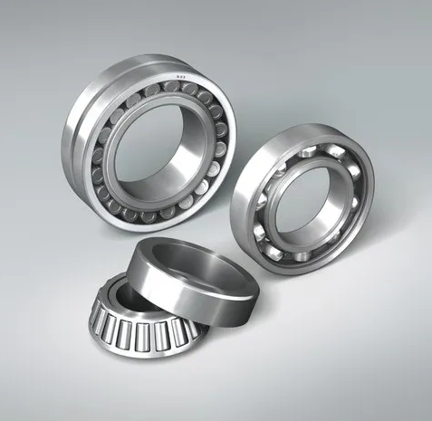
Bearings are the most common components dealing with radial forces. In machinery, they support rotating shafts and handle loads applied perpendicular to the axis of rotation. Radial force in bearings typically arises from the contact between rolling elements (e.g., balls or rollers) and the raceways of the inner and outer rings. - Gears
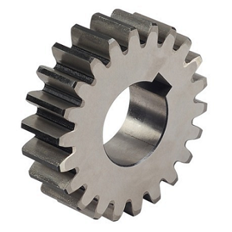
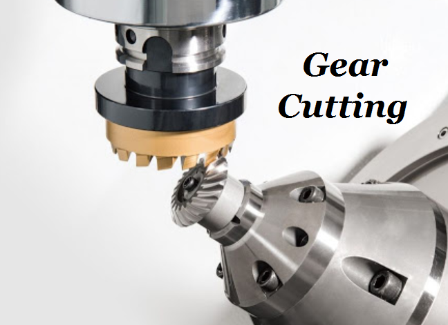
In gear systems, radial forces are generated during torque transmission through the gear teeth. When gears engage, the force acting on the teeth creates a radial component directed toward the center of the gears. - Shafts
Shafts experience radial forces when subjected to bending loads. These forces are typically caused by the weight of attached components or torsional forces that produce bending moments. - Springs
In systems with springs, such as suspensions, springs exert radial forces when oriented to compress or expand radially relative to the system’s central axis. - Belts and Pulleys
In belt-driven systems, belt tension creates radial forces on the pulleys. The tension pulls at the pulley contact points, generating an inward radial force toward the pulley’s shaft. - Pistons and Cylinders
In engines and pumps, pistons create radial forces against cylinder walls due to gas or fluid pressure acting on the piston face. The cylinder walls provide a reactive radial force to maintain linear piston motion. - Flanges and Bolts
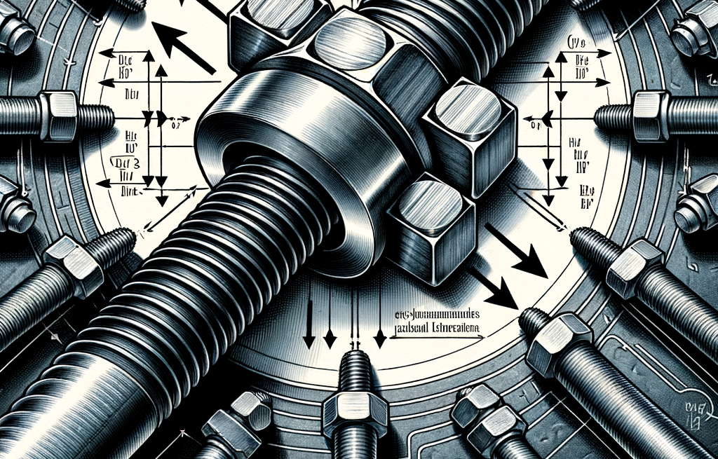
In flanged connections (e.g., pipes), bolts may experience radial forces when misalignment or thermal expansion causes radial loads on the bolts. - Electromagnetic Forces
In electric motors and generators, radial forces can arise from interactions between magnetic fields of the stator and rotor. These forces influence the rotor and require robust bearing systems to manage.
Effects of Radial Force
Radial force significantly impacts the following aspects of mechanical components:
- Strength and Stiffness
Radial force can cause bending, deformation, or fracture of parts. Therefore, materials and structural stiffness must meet design requirements. - Friction and Wear
Radial force affects the friction properties of contact surfaces, influencing wear rates and component lifespan. - Shear and Load Distribution
Radial force directly affects shear strength and load distribution, particularly in complex connections or multi-point support structures. - Stability
Radial force is crucial for the balance of rotating parts and the overall stability of the system.
To optimize performance, service life, and reliability, designers must account for the effects of radial force. For example, in bearing design, proper distribution and optimization of radial force can reduce fatigue damage and extend service life.
Radial Force Formula and How To Calacute
Radial force in mechanical design refers to the force acting on a component perpendicular to its axis. This force is common in bearings, gears, turbines, and other rotating equipment. Different components have different formulas for calculating radial force. Below are detailed explanations for calculating radial forces in bearings and bolts.
1. Radial Force Calculation in Bearings
Radial force in bearings refers to the perpendicular load acting on the bearing axis. Bearings are designed to support rotating shafts or components and bear forces caused by loads (including radial and axial forces).
Formula:
Radial force in bearings is often calculated based on the specific application. The most common scenario involves forces generated by other components, such as gears, pulleys, or motors. For example, if a shaft supported by a bearing is subjected to a gear’s radial force, it can be calculated as follows:
Fr = Ft × tan(α)
Where:
- Fr = radial force
- Ft = tangential force (from torque transmitted through the gear)
- α = pressure angle of the gear (angle between the load direction and a plane perpendicular to the bearing axis)
Steps to Calculate Radial Force in Bearings:
- Determine Tangential Force (Ft):
Calculate Ft using the transmitted torque T and gear radius r:Ft = T / r - Identify the Pressure Angle (α):
This is a design parameter of the gear, typically provided in the gear’s technical specifications. - Apply the Formula:
Substitute the known values into the formula to calculate Fr.
Example:
A gear system has a pressure angle of 20°, a transmitted torque of 500 Nm, and a gear radius of 0.1 m.
- Calculate tangential force:
Ft = 500 / 0.1 = 5000 N - Calculate tan(20°):
tan(20°) ≈ 0.364 - Calculate radial force:
Fr = 5000 × 0.364 = 1820 N
The radial force generated by this gear on the shaft is 1820 N.
2. Radial Force Calculation in Bolts
Radial forces on bolts are less commonly considered compared to axial forces and preload. However, in flange connections, radial forces may result from eccentric loads or misalignment.
Formula:
For eccentric loads causing radial force on bolts:
Fr = F × e / d
Where:
- Fr = radial force on each bolt
- F = external load
- e = eccentric distance
- d = diameter of the bolt circle
Example:
A flange connection has 4 bolts, an external load of 800 N, an eccentric distance of 0.1 m, and a bolt circle diameter of 0.4 m.
- Calculate radial force:
Fr = 800 × 0.1 / 0.4 = 200 N
Each bolt experiences a radial force of 200 N.
Radial Force Testing
Testing radial force often requires specialized equipment and techniques. Common methods include:
- Force Sensors (Load Cells): Directly measure force at specific points.
- Strain Gauges: Measure deformation to infer force.
- Test Rigs: Simulate operating conditions under controlled environments.
- Finite Element Analysis (FEA): Simulate forces and stresses using computer models.
- Dynamic Measurement Systems: Monitor forces during actual operation.
Radial Force vs. Axial Force
In mechanical design, radial force and axial force are two basic forces that describe the direction of force acting on mechanical elements. Here we use a table to show the main differences between them:
| Aspect | Radial Force | Axial Force |
|---|---|---|
| Direction | Perpendicular to the axis, along the radius. Example: In bearings, radial force acts inward or outward through the shaft. | Parallel to the axis, along the length of the shaft. Example: In a bolt, axial force is the tension or compression along its axis. |
| Affected Components | Common in rotating components such as bearings, gears, turbine blades, etc., which must withstand side or external forces. | Common in components like bolts, piston mechanisms, thrust bearings, or thrusters, which handle compression or tension forces. |
| Main Considerations | Critical in rotating equipment design due to its impact on shaft bending, bearing loads, and dynamic balance. | Important in systems involving push or pull, such as bolted connections or thrust bearings, as it affects stability and tightness. |
| Calculation and Analysis | Requires load distribution analysis on rotating parts, focusing on shaft bending and bearing load. Dynamic analysis software is often used. | Focuses on reducing adverse effects through design, such as using thrust bearings or sufficient preload to prevent bolt loosening. |
| Application Example | Motor Bearings: Radial forces generated during motor rotation affect bearing selection and lifespan. | Anchor Bolts in Bridges: Axial forces from structural weight and use loads determine bolt design and stability. |


