Straight turning is one of the turning processes that can be performed on a lathe machine, how does it work, and how to complete the operation? This article will explain the straight (plain) turning about its principle, uses, operation, tools, diagram, and differences compared to step turning.
What Is Straight Turning in Lathe Machine?
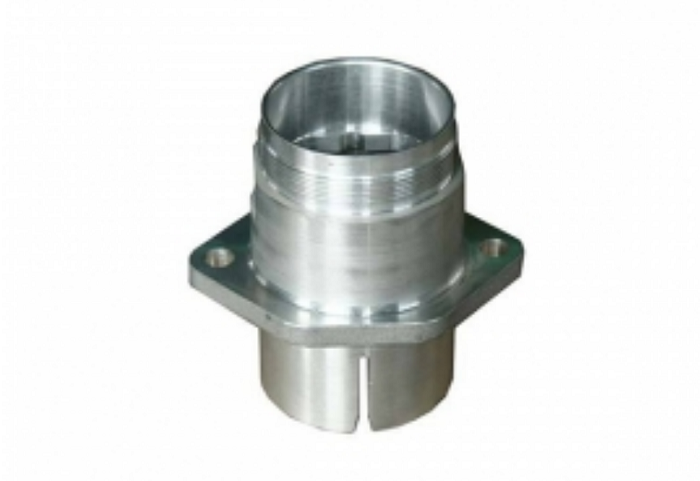
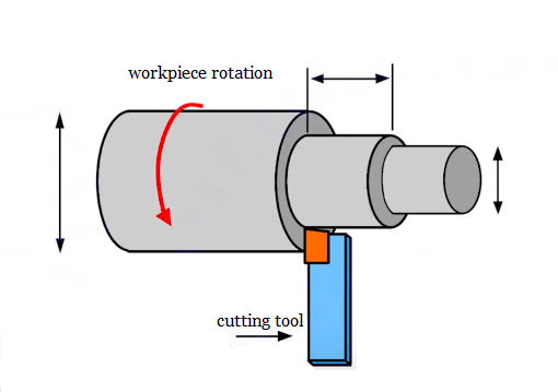
Straight turning, also known as plain turning or cylindrical turning, is a fundamental lathe operation where a workpiece secured in a chuck, rotates about its axis while a cutting tool moves parallel to this axis. Plain turning is a specialized technique originating from the watch industry, that uses a guide sleeve to support long, slim workpieces. The material is fed through the sleeve, allowing for precise, extended-length turning.
Straight turning process uniformly reduces the workpiece’s diameter by removing excess metal from its surface. It’s typically employed as a roughing operation, efficiently eliminating substantial amounts of material before more precise cuts are made. The consistent motion of the tool along the workpiece’s length ensures a uniform diameter throughout the cut, resulting in a cylindrical surface. This technique can be performed with the workpiece held either in a chuck or between centers, with the cutting tool advancing longitudinally to shape the desired cylindrical form. Straight turning is usually used to produce turned parts like shafts, rods, and pins.
Straight Turning Operation & Process on the Lathe
Straight turning is a type of turning operation where excess material is removed from the workpiece to generate a cylindrical surface.
Equipment Setup:
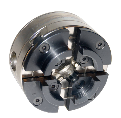
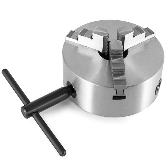
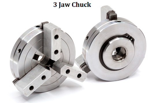
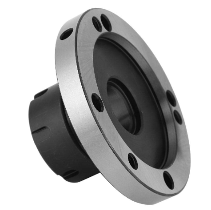
– Chuck selection: Choose an appropriate chuck based on the workpiece size. This ensures a firm grip on the material during machining.
– Workpiece mounting: Securely fasten the workpiece in the chuck, ensuring it’s centered and properly aligned.
– Tool positioning: Set up the cutting tool on the tool post, positioning it perpendicular to the workpiece’s axis.
Operation Steps or Process:
1. Determine the required final diameter and length of the workpiece.
2. Calculate the amount of material to be removed.
3. Set the lathe’s spindle speed according to the material and cutting tool specifications.
4. Engage the feed mechanism to move the cutting tool along the workpiece’s axis.
5. Begin the cutting process, removing material along the circumference and length of the workpiece in a straight line.
6. Monitor the cutting process, ensuring proper chip formation and surface finish.
7. Make multiple passes if necessary, gradually approaching the final dimensions.
8. Use measuring tools such as calipers and micrometers to verify the achieved diameter periodically.
Note and Limitations
Plain turning typically has a workable diameter limit of about 32 mm due to the guide sleeve arrangement. In plain turning, the final contour must be achieved in a single pass, as retracting the material through the guide sleeve would compromise guidance for subsequent cuts.
Straight Turning Diagram
Straight Turning Tools
During straight or plain turning operations on a machine, the types of cutting tools commonly used include high-speed steel (HSS) tools, hard alloy (Carbide) tools, and Stellite tools.
– High-speed steel tools: This is the most common choice, suitable for the shaping operations of most metal materials. Its advantages are low cost and ease of manufacture, but it requires a high cutting speed to avoid overheating and wear.
– Hard alloy tools: This type of tool has higher hardness and wear resistance, making it suitable for high-efficiency and high-precision shaping tasks. They are often used in scenarios requiring high-speed shaping or working in high-temperature environments.
– Stellite tools: Stellite is a special wear-resistant alloy, particularly suitable for the shaping of hard materials. It can maintain good performance under extreme conditions and is therefore commonly used for high-difficulty operations.
Plain Turning vs Step Turning, What Are the Differences
1) Workpiece geometry:
– Plain turning produces a cylindrical workpiece with a uniform diameter.
– Step turning creates a part with a series of stepped surfaces.
2) Cutting tool movement:
– Plain turning: The cutting tool moves longitudinally along the workpiece, removing material in a straight line.
– Step turning: The cutting tool is adjusted to different positions during the turning operation.
3) Diameter:
– Plain turning: The diameter of the workpiece is reduced to a specific dimension, but the diameter remains uniform throughout the length of the workpiece.
– Step turning: The diameter of the workpiece varies along the length.
4) Applications:
– Plain turning is used to manufacture cylindrical parts, such as shafts, axles, and pipes.
– Step turning is often applied to create pulleys, gears, and bearings.
5) Tooling and setup:
– Plain turning typically uses a standard turning tool and a chuck.
– Step turning requires a specialized tooling setup, such as a V-cutting tool, and a more complex setup.


